MAXCS Release 7.
Contents Contents ............................................................................................................................................................................ 2 About This Guide............................................................................................................................................................... 3 Related Documents ...........................................................................................................................
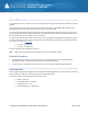
About This Guide This guide explains how to configure one or more analog extensions using an AudioCodes VoIP SIP MP-11x or MP-124 gateway. These instructions will work behind most on-premise firewalls, NAT routers, and EdgeMarc SBCs. MaxCS and the AudioCodes gateway can be on the same LAN or can be inter-connected via VPN. The examples in this guide illustrate the configuration for an AudioCodes MP -118 gateway.
Figure 1: Diagram of MaxCS, Firewall/NAT, and AudioCodes gateway Prerequisites To set up analog extensions using an AudioCodes MP-11x or MP-124 gateway, you must meet the following requirements: • You must be running either MaxCS Release 7.0 Enterprise or MaxCS Private Cloud. • Proper configuration for MaxCS behind NAT is required (including the port forwarding and Enterprise Manager settings). Any AltiGen IP phones behind NAT should already be working correctly behind the on-premise firewall.
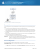
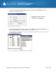
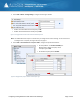
2. On the General tab, configure the following settings. • Check Enable IP Extension. • Check Connect Voice Stream to Server. (If you clear this checkbox, conferences will fail.) • Check Enable 3rd Party SIP Device. • Enter a SIP Registration Password. We use 5656 in this example. Figure 2: Configure IP Extension settings 3. Select PBX > AltiGen IP Phone Configuration. 4. For extension 167, clear the checkbox Enable SIP Telephony Service. Figure 3: Disable SIP Telephony Service 5.
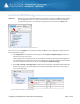
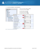
. Select VoIP > Enterprise Network Management > Servers > IP Codec > IP Device Range. Add the Firewall/NAT's public IP address range. • Set both the From and the To fields to 10.40.0.95 (as shown in Figure 1) • For the Codec, select OnPremise. Figure 5: Configure the IP Device range 7. Open the MaxAdministrator Boards view. Double click the SIPSP entry, select Board Configuration, and click Advanced Configuration. Add 10.40.0.95 to the Trusted SIP Device List.
AudioCodes MP-118 Configuration Important! While working in the AudioCodes configuration application, make sure that Full is always selected for the Configuration menu, so that you can see all of the menu options. Check this setting after you log out and log back in, as sometimes the application can reset the menus to Basic mode.
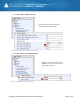
3. Select VoIP > Media > RTP/RTCP Settings. • Set both RFC 2833 TX Payload Type and RFC 2833 RX Payload Type to 101. Figure 9: Configure the Media RFC 2833 Payload settings 4. Select VoIP > Media > General Media Settings. • Make sure that NAT Traversal is set to Disable, so that it will not conflict with MaxCS’s NAT Traversal.
5. Select VoIP > Media > Analog Settings. Configure the settings as follows: • Set Min. Hook-Flash Detection Period [msec] to 300. • Set Max. Hook-Flash Detection Period [msec] to 800. Figure 11: Configure the minimum and maximum detection periods Note: The AudioCodes device requires a reboot after you change either of these settings. You can reboot once all configuration is complete, during the last step on page 17. 6. Select VoIP > Control Network > Proxy Sets Table.
7. Select VoIP > SIP Definitions > General Parameters. • Make sure that NAT IP Address is 0.0.0.0. • Set Enable Early Media to Disable. • Set SIP Transport Type to UDP. • Set SIP UDP Local Port to 10060. • Set SIP Destination Port to 10060.
8. Select VoIP > SIP Definitions > Proxy & Registration. • Set Use Default Proxy to Yes. • Set Enable Registration to Enable. • Set Registrar IP Address to 10.40.1.43. (The MaxCS public IP address.) • Set Registrar Transport Type to UDP. • Set Registration Time to 100. • Set Re-registration Timing [%] to 50.
9. Select VoIP > Coders and profiles > Coders. Make sure that both G.711U-law and G.729 are in the list. Figure 15: Confirm that G.711U-law and G.729 are listed in Coders and Profiles 10. Select VoIP > GW and IP to IP > Hunt Group > Endpoint Phone Number. Configure Entry 1 as follows. • Set Channel(s) to 1. (This means the first FXS port.) • Set Phone Number to 167 (refer to the extension in Figure 1). • Set Hunt Group ID to 1. • Set Tel Profile ID to 0.
11. Select VoIP > GW and IP to IP > Hunt Group > Hunt Group Settings. Configure Entry 1 as follows. • Enter 1 for the Hunt Group ID. • Set Channel Select Mode to By Dest Phone Number. • Set Registration Mode to Per Endpoint. • Make sure Serving IP Group ID is blank. Figure 17: Configure hunt group settings 12. Select VoIP > GW and IP to IP > Routing > IP to Hunt Group Routing. Configure Entry 1 as follows: • Set the first five fields, Dest. Host Prefix, Source Host Prefix, Dest.
13. Select VoIP > GW and IP to IP > DTMF and Supplementary > DTMF & Dialing. • Set Declare RFC 2833 in SDP to Yes. • Set 1st Tx DTMF Option to RFC 2833. • Set RFC 2833 Payload Type to 101. • Set Hook-Flash Option to INFO (NetCentrex). • If your MaxCS extension length is 3 digits, set Digit Mapping Rules to 911|##|[1-7]XX|#XX|9[2-9]XXXXXX|91[2-9]XXXXXXXXX|XX.T • If your MaxCS extension length is 4 digits, set Digit Mapping Rules to 911|##|[1-7]XXX|#XX|9[2-9]XXXXXX|91[2-9]XXXXXXXXX|XX.
. You can turn on the Message Waiting lamp if your analog phones support MWI. When a user has a new voicemail message, the MWI lamp will flash. Note that enabling the MWI lamp will increase SIP messages for each configured FXS port. Skip this step if you do not want to implement this feature.
17. Select VoIP > GW and IP to IP > Analog Gateway > Caller ID Permissions. Enable for Caller ID for all ports. Figure 23: Enable Caller ID 18. Select VoIP > GW and IP to IP > Analog Gateway > Authentication. Configure the entry Port 1 FXS as follows: • Set User Name to 167. • For the password, enter 5656. (This is the extension and password you set up on page 4.) Note: If you save and then restore the .
19. (Optional) If you want to set up E911 Location ID for relocation for the gateway, select VoIP > GW and IP to IP > Analog Gateways > Authentication.
2. Click the Register button. Figure 27: Register the phone extension 3. Log into MaxCS 7.0 MaxAdministrator. Open the Extension view; extension 167 should be listed there. Figure 28: The extension appears in Extension View in MaxCS Administrator 4. Attach an analog phone to the first FXS port and make a few calls to test that everything works correctly. 5.
• For the INI file, upload “usa_tones_13_NoHold.ini" • For the Call Progess Tones file, upload "usa_tones_13_NoHold.dat" Figure 29: Upload the INI and DAT files 6. Submit this last change. On the toolbar, click Burn. 7. Restart the AudioCodes gateway. The INI File Here are the contents of the usa_tones_13_NoHold.ini file.
Low Freq [Hz]=440 High Freq [Hz]=0 Low Freq Level [-dBm]=10 High Freq Level [-dBm]=32 First Signal On Time [10msec]=300 First Signal Off Time [10msec]=0 Second Signal On Time [10msec]=0 Second Signal Off Time [10msec]=0 #Ringback [CALL PROGRESS TONE #2] Tone Type=2 Tone Form =2 Low Freq [Hz]=440 High Freq [Hz]=480 Low Freq Level [-dBm]=19 High Freq Level [-dBm]=19 First Signal On Time [10msec]=0 First Signal Off Time [10msec]=0 Second Signal On Time [10msec]=200 Second Signal Off Time [10msec]=400 #Ringback
[CALL PROGRESS TONE #5] Tone Type=3 Tone Form =2 Low Freq [Hz]=440 High Freq [Hz]=0 Low Freq Level [-dBm]=20 High Freq Level [-dBm]=32 First Signal On Time [10msec]=50 First Signal Off Time [10msec]=50 Second Signal On Time [10msec]=50 Second Signal Off Time [10msec]=50 #Reorder tone [CALL PROGRESS TONE #6] Tone Type=7 Tone Form =2 Low Freq [Hz]=480 High Freq [Hz]=620 Low Freq Level [-dBm]= 24 High Freq Level [-dBm]=24 First Signal On Time [10msec]=25 First Signal Off Time [10msec]=25 Second Signal On Time
First Signal Off Time [10msec]=10 Second Signal On Time [10msec]=10 Second Signal Off Time [10msec]=10 #Call Waiting Tone [CALL PROGRESS TONE #9] Tone Type=9 Tone Form =2 Low Freq [Hz]=440 High Freq [Hz]=0 Low Freq Level [-dBm]=20 High Freq Level [-dBm]=32 First Signal On Time [10msec]=0 First Signal Off Time [10msec]=0 Second Signal On Time [10msec]=30 Second Signal Off Time [10msec]=500 #Stutter Dial tone [CALL PROGRESS TONE #10] Tone Type=15 Tone Form =1 Low Freq [Hz]=350 High Freq [Hz]=480 Low Freq Leve
Low Freq Level [-dBm]=19 High Freq Level [-dBm]=19 First Signal On Time [10msec]=120 First Signal Off Time [10msec]=40 Second Signal On Time [10msec]=40 Second Signal Off Time [10msec]=400 ;#Hold Tone ;[CALL PROGRESS TONE #13] ;Tone Type=23 ;Tone Form =2 ;Low Freq [Hz]=1400 ;High Freq [Hz]=0 ;Low Freq Level [-dBm]=15 ;High Freq Level [-dBm]=32 ;First Signal On Time [10msec]=0 ;First Signal Off Time [10msec]=0 ;Second Signal On Time [10msec]=40 ;Second Signal Off Time [10msec]=500 # Ringing signal [NUMBER OF
Known Limitations and Workarounds Following are known limitations and workarounds that you should consider while managing your gateway connections. • Analog connections were validated and certified against firmware version 6.60A.265.010. Using other firmware versions could result in a loss of dial tone. • If you power up an MP-118 gateway while it is not connected to the network, then you later attach the network connection or uplink switch, some of the channels may not be able to register.
• Number and types of boards in the system • Server model • The telephone number where you can be reached Configuring Analog Extensions with AudioCodes Gateways Page 25 of 25