SPECIAL APPLICATION MANUAL PART NUMBER: 400-0210-001 PE1004CF CAT-5 RECEIVER CARD FOR PIONEER PLASMA EXPANSION USER’S GUIDE
SPECIAL APPLICATION TABLE OF CONTENTS Page PRECAUTIONS / SAFETY WARNINGS ............... 2 GENERAL..........................................................2 INSTALLATION .................................................2 CLEANING.........................................................2 HANDLING ........................................................2 FCC / CE NOTICE..............................................2 ABOUT YOUR PE1004CF ....................................... 3 TECHNICAL SPECIFICATIONS ......
SPECIAL APPLICATION PRECAUTIONS / SAFETY WARNINGS 1.5 FCC / CE NOTICE 1 Please read this manual carefully before using your PE1004CF. Keep this manual handy for future reference. These safety instructions are to ensure the long life of your PE1004CF and to prevent fire and shock hazard. Please read them carefully and heed all warnings. • 1.1 GENERAL • • There are no user-serviceable parts on this unit. Qualified ALTINEX service personnel must perform all service on the PE1004CF. 1.
SPECIAL APPLICATION ABOUT YOUR PE1004CF 2 TECHNICAL SPECIFICATIONS PE1004CF CAT-5 RECEIVER CARD FOR PIONEER PLASMA EXPANSION FEATURES/ DESCRIPTION GENERAL Input Connectors CAT-5 Video+ Audio Audio, Stereo Unbalanced Video, RGBHV RS-232 Output Connectors CAT-5 Video+ Audio Audio, Stereo, Unbalanced Video, RGBHV Compatibility Video Audio The PE1004CF CAT-5 Receiver Card is designed to receive RGBHV/YPbPr video and audio signals over twisted pair (CAT-5) type cable.
SPECIAL APPLICATION DESCRIPTION OF PE1004CF 4 APPLICATION DIAGRAMS 5 DIAGRAM 1: INPUT SELECTION AUTOMATIC INPUT SELECTION Selecting plasma Input 3 displays PE1004CF CAT-5 #1 Input image on the plasma Input 3. Selecting plasma Input 4 displays PE1004CF CAT-5 #2 Input image on the plasma Input 4. Selecting plasma Input 5 displays PE1004CF CAT-5 #3 Input image on the plasma Input 5.
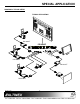
SPECIAL APPLICATION DIAGRAM 2: TYPICAL SETUP TYPICAL APPLICATION DA1930CT PE1004CF RS -23 2 DA1930CT DA1931CT DA1930CT 400-0210-001 5
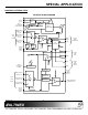
SPECIAL APPLICATION DIAGRAM 3: INTERNAL VIEW PE1004CF BLOCK DIAGRAM CONTROL TX RS232 3P TB RS232 TO TTL RX EDGE CONNECTOR BUS CONTROL RS232 CAT5 S/W MICRO CONTROLLER H/W EQ EQ VIDEO INPUT 1 PAIRS 1,2,3 of UTP CONTROL CAT5 RJ45 VIDEO INPUT 2 PAIRS 1,2,3 of UTP + - (RGB/ YPbPr) VIDEO VIDEO INPUT 3 PAIRS 1,2,3 of UTP SYNC INPUT4 15P HD RGBHV/ Y,Pb,Pr SYNC PROCESSING CONTROL SIGNAL DETECT PNP CONTROL PAIR1,2,3 OUTPUT CAT5 RJ45 RS232 CAT5 PAIR 4 CONTROL POWER SUPPLY AUDIO INPUT 1 PAIR
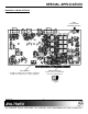
SPECIAL APPLICATION DIAGRAM 4: SWITCH SETTINGS VIDEO EQUALIZATION HARDWARE CONTROL SW2 EQ POWER UP DEFAULT Install the jumper for default input. In this case, CAT-5 Input #1. EQUALIZATION Set SW2 to the HW position for hardware equalization. Set SW2 to the SW position for software equalization.
SPECIAL APPLICATION INSTALLING YOUR PE1004CF 6 OPERATION Step 1. Use ESD safety precautions and always wear a ground strap when handling the PE1004CF expansion card. 7.1 RS-232 CONTROL The PE1004CF has many advanced remote control capabilities which are accessible through standard RS-232 communication. Actual controlling may be achieved using a computer control system or other device capable of sending RS-232 commands. Step 2. Prepare the card per the drawing in Diagram 4.
SPECIAL APPLICATION Example: 1. [SIDn] Send the command [VER] and receive the following feedback: PE1004CF 690-0207-001 PE1004CF = Model Number 690-0207-001 = Firmware Version This command sets the ID number of the unit. The default unit ID is zero. Command Format: [SIDn] n = Unit ID (n = # from 0 to 99) Example: 5. [STATUS] Send the command [SID1] to the system. The unit ID is now one, and “C1” must be included at the end of each command line, as in “[VERC1]”, for only the unit with ID1 to respond.
SPECIAL APPLICATION 7. [IN] 10. [ + ] This command is used to select the PE1004CF input that will be directed to the plasma display’s active expansion input. Command Format: [INnCi] This command increments a selected property, in this case equalization, to be adjusted using RS-232 control.
SPECIAL APPLICATION 12. […S] TROUBLESHOOTING GUIDE This command will save the configuration command being sent to the PE1004CF into its nonvolatile memory. Example: Equalization We have carefully tested and have found no problems in the supplied PE1004CF. However, we would like to offer suggestions for the following: 8.1 NO DISPLAY If Input 4 is currently the active input, send the command [EQ100S] to save the equalization value of 100 for this input.
SPECIAL APPLICATION Cause 3: Solution: Cable connections are incorrect. Make sure that the cables are connected properly. Also, make sure that the continuity and wiring are good. If there is still no sound present, see Cause 4. Cause 4: Destination amplifier has a problem. Solution 1: Make sure that the destination amplifier is powered. If there is still no sound, see Solution 2 Solution 2: Set the volume of the destination amplifier to a reasonable level.