DISTRIBUTION AMPLIFIERS MANUAL PART NUMBER: 400-0016-004 DA1506RT 2-IN, 6-OUT VGA DISTRIBUTION AMPLIFIER USER’S GUIDE
DISTRIBUTION AMPLIFIERS TABLE OF CONTENTS Page PRECAUTIONS / SAFETY WARNINGS................ 2 GENERAL..........................................................2 RACK-MOUNTING SAFETY GUIDELINES........2 HANDLING ........................................................2 CLEANING.........................................................2 FCC NOTICE .....................................................2 ABOUT YOUR DA1506RT ....................................... 3 TECHNICAL SPECIFICATIONS.......................
DISTRIBUTION AMPLIFIERS PRECAUTIONS / SAFETY WARNINGS 1 Please read this manual carefully before using your DA1506RT Distribution Amplifier. Keep this manual handy for future reference. These safety instructions are to ensure the long life of your DA1506RT and to prevent fire and shock hazards. Please read them carefully and heed all warnings. Qualified ALTINEX service personnel or its authorized representatives must perform all service. The maximum operating ambient temperature for this unit is 35°C.
DISTRIBUTION AMPLIFIERS ABOUT YOUR DA1506RT 2 MECHANICAL DA1506RT 2-In, 6-Out Distribution Amplifier (DA) Material 1.75 in (44mm) Width (inches) 8.50 in (216mm) Depth (inches) 4.50 in (114mm) 2.0 lb (0.91 kg) T° Operating 10°C-35°C T° Maximum Humidity 50°C 90% non-condensing 40,000 hrs Table 2. DA1506RT Mechanical ELECTRICAL DA1506RT Input Video Signal Analog Signal Impedance 1.5 Vp-p max 75 ohms Input Sync Signal Horiz/Vert/Composite Sync Sync on Green Impedance TTL(+/-) -0.
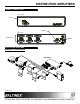
DISTRIBUTION AMPLIFIERS PRODUCT DESCRIPTION 4 FRONT VIEW INPUT1 INPUT2 REAR VIEW OUTPUTS 1-6 POWER APPLICATION DIAGRAMS 5 DIAGRAM 1: TYPICAL SETUP DA1506RT 400-0016-004 4
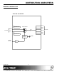
DISTRIBUTION AMPLIFIERS DIAGRAM 2: INTERNAL VIEW 2-IN 6-OUT VGA-XGA DA OUT 1 PLUG AND PLAY AUTO SWITCH OUT 2 FRONT OUT 3 BACK OUT 4 15-PIN HD OUT 5 PLUG AND PLAY OUT 6 SIGNAL DETECT POWER 9V, 0.
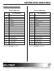
DISTRIBUTION AMPLIFIERS DIAGRAM 3: CONNECTOR PINOUTS INPUT CONNECTORS Pin No. OUTPUT CONNECTORS PIN ASSIGNMENTS Pin No.
DISTRIBUTION AMPLIFIERS INSTALLING YOUR DA1506RT 6 TROUBLESHOOTING GUIDE Step 1. Plug the power adapter into an AC receptacle. We have carefully tested and found no problems in the supplied DA1506RT; however, we would like to offer suggestions for the following: Step 2. Connect the power to the unit. The power indicator LEDs on the front and back panels will turn on and red. This indicates that the unit is operational. Step 3.