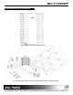
MULTI-TASKER MT105-112 is shown above.
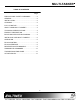
MULTI-TASKER TABLE OF CONTENTS Page PRECAUTIONS / SAFETY WARNINGS ...............2 GENERAL .............................................................2 INSTALLATION.....................................................2 CLEANING ............................................................2 FCC / CE NOTICE .................................................2 ABOUT YOUR MULTI-TASKER™ ........................3 TECHNICAL SPECIFICATIONS............................3 PRODUCT DESCRIPTION ............................
MULTI-TASKER PRECAUTIONS / SAFETY WARNINGS 1 Please read this manual carefully before using your MT105-112/119. Keep this manual handy for future reference. These safety instructions are to ensure the long life of your MT105-112/119 and to prevent fire and shock hazard. Please read them carefully and heed all warnings. 1.1 GENERAL • • Qualified ALTINEX service personnel, or their authorized representatives must perform all service. 1.
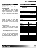
MULTI-TASKER ABOUT YOUR MULTI-TASKER™ 2 TECHNICAL SPECIFICATIONS MT105-112/MT105-119 16-in 16-out Sync and Video Matrix Switcher Cards FEATURES/ DESCRIPTION GENERAL Inputs External Input Connectors The MT105-112 16-in, 16-out Video Matrix Switcher card is designed for use in the MultiTasker enclosure to allow the routing of computer and broadcast video in audio/visual presentation systems.
MULTI-TASKER BLOCK AND APPLICATION DIAGRAM 4 Block diagram of MT105-112/MT105-119 Up to 16 inputs and outputs can be connected and switched using these cards.
MULTI-TASKER INSTALLING YOUR MULTI-TASKER™ 5 6.2 DESCRIPTION OF COMMANDS Each command consists of three parts: function, card ID, and unit ID. [Function, Card ID, Unit ID]. Step 1. Slide the MT105-112/119 into an available slot in the Multi-Tasker™ Enclosure in order to connect to the bus. Make sure that the MT105-112/119 card fits into place. Secure the card to the MultiTasker™ by tightening the retainer screws located on the top and bottom of the MT105-112/119 card. Step 2.
MULTI-TASKER Cn = card ID (n = a slot # from 1 to 19) This command saves card status as default configuration, such as ON / OFF, IN / OUT. The next time card will be activated this configuration will be loaded in. (1 to 8 for MT100-101 or 1 to 2 for MT100-102) Ui = unit id (i = 0 to 9) (refer to the MT100-100 user’s guide for explanation) 4.
MULTI-TASKER 2) [ON3C5U3]: Turns ON only output 3 of the MT105-112/119 card located in slot #5 of the MT100-100 Enclosure with unit ID3. After the [ON12C5U3] and [ON3C5U3] commands have been executed, output 1, 2 and 3 will be ON. 3) [ONC5U3]: Turns ON all outputs of the card. [ONmGkUiS]: for a group of cards This command enables output "m" for each card in group "k" of unit "i".
MULTI-TASKER on multiple cards or the same card can be loaded. Command Format: [OFFmCnUiP] m = output number (m =1 to 16) n = card ID No. (n = a slot # from 1 to 19) (1 to 8 for MT100-101 or 1 to 4 for MT100-106) P = path Example: If 2 cards are at slot 4 and 8 of unit 3: To enable output 1 and 2 of card 4 and output 3 and 4 of card 8 simultaneously, use the following commands: [OFF12C4U3P] [OFF34C8U3P] [SW] If "F" is included use the [OFFmCnUiPF] command or the [OFFmCnUiFP] command. n = card ID No.
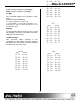
Input O5a O5b O6a O6b O7a O7b O8a O8b 1)[G1]: will return feedback as [On123G1]. 2)[G2]: will return feedback as [On2G2]. 11. [RD] This command displays the members in each group.
MULTI-TASKER 2x2 Input O2a O2b O2c O2d O2e O2f O2g O2h O1a O1b O1c O1d O1e O1f O1g O1h KEY 2: to select outputs (use a single key to select different outputs). KEY 3: to select card for link factor (use a single key to select different cards). When the MT105-112/119 receives this kind of command, it will wait until third command string received (CiMx..]) and then, will link the commands together by looking at CiMx group.Each command can be as long as 42 characters.
MULTI-TASKER 6.3. SUMMARY OF COMMANDS 7.1 NO DISPLAY 1) [VER]: Receives software version A) Cause 1: The source has a problem. 2) [C]: Receives status of the card Solution: Check the source and make sure hat there is a signal present and all source connections are correct. If the source is working and there is still no display, see Cause 2. 3) [CS]: Saves status of the card as default configuration 4) [IO]: Connects the input to the output B) Cause 2: The card input is not selected.