MULTITASKER™ MT113-100 MT113-101 MANUAL PART NUMBER: 400-0209-002 MT113-100/101 3-IN MIXER 1-OUT, + 15W STEREO AUDIO POWER AMPLIFIER CARD FOR MULTITASKER USER’S GUIDE
MULTITASKER™ TABLE OF CONTENTS Page PRECAUTIONS / SAFETY WARNINGS ............... 2 GENERAL..........................................................2 CLEANING.........................................................2 FCC / CE NOTICE..............................................2 ABOUT YOUR MT113-100/101............................... 3 TECHNICAL SPECIFICATIONS ............................ 3 DESCRIPTION OF MT113-100/101 ....................... 4 APPLICATION DIAGRAMS......................................
MULTITASKER™ PRECAUTIONS / SAFETY WARNINGS • 1 Please read this manual carefully before using your MT113-100/101. Keep this manual handy for future reference. These safety instructions are to ensure the long life of your MT113-100/101 and to prevent fire and shock hazard. Please read them carefully and heed all warnings. 1.1 GENERAL • Qualified ALTINEX service personnel, or their authorized representatives must perform all service. • To prevent fire or shock, do not expose this unit to rain or moisture.
MULTITASKER™ ABOUT YOUR MT113-100/101 2 TECHNICAL SPECIFICATIONS MT113-100/101 3 in Mixer, 1 fixed line level output and 30W amplifier Card FEATURES/DESCRIPTION GENERAL Inputs Input Connectors The MT113-100/101 is a Stereo Audio Power Amplifier Card designed for use with the MultiTasker. This card allows the connection of up to two line level balanced/unbalanced inputs and one microphone. The card has a built-in, dual 15W, power amplifier.
MULTITASKER™ DESCRIPTION OF MT113-100/101 4 MT113-100 DESCRIPTION 400-0209-002 4 4
MULTITASKER™ MT113-101 DESCRIPTION 400-0209-002 5 5
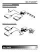
MULTITASKER™ APPLICATION DIAGRAMS 5 DIAGRAM 1: MT113-100 TYPICAL SETUP DIAGRAM 2: MT113-101 TYPICAL SETUP 400-0209-002 6 6
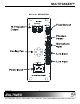
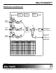
MULTITASKER™ DIAGRAM 3: MT113-100 INTERNAL VIEW PHANTOM POWER MP CONTROL POWER SUPPLY SW5 M+ SW4 M- MIC LINE/MIC INPUT1 BALANCED SW1 S/W GAIN SW7 M+ VOLUME BASS TREBLE SW6 M- MIC LINE/MIC INPUT2 BALANCED S SW2 S/W GAIN 70V X-FORMER S/W GAIN 70V/30W MONO SPEAKER OUTPUT PUSH CONNECTOR SW9 M+ SW8 M- MIC LINE/MIC INPUT3 BALANCED SW10 SW3 S/W GAIN INPUT1 LINE MIC INPUT2 PHANTOM POWER OFF ON + + LINE MIC INPUT3 PHANTOM POWER OFF ON + + LINE MIC LINE OUTPUT PHANTOM POWER OFF ON + +
MULTITASKER™ DIAGRAM 4: MT113-101 INTERNAL VIEW x PHANTOM POWER MP CONTROL POWER SUPPLY SW5 M+ SW4 M- MIC LINE/MIC INPUT1 BALANCED SW1 S/W GAIN SW7 M+ VOLUME BASS TREBLE SW6 M- MIC S SW2 LINE/MIC INPUT2 BALANCED S/W GAIN 15W STEREO SPEAKER OUTPUTS PUSH CONNECTOR S/W GAIN SW9 M+ SW8 MSW10 MIC SW3 LINE/MIC INPUT3 BALANCED S/W GAIN INPUT1 LINE MIC INPUT2 PHANTOM POWER OFF ON + + LINE MIC INPUT3 PHANTOM POWER OFF ON + + LINE MIC LINE OUTPUT PHANTOM POWER OFF ON + + FIX ADJ SW1
MULTITASKER™ INSTALLING YOUR MT113-100/101 Step 1. Turn off power enclosure. to the Commands ending in "S" will be saved into memory. Commands not ending in "S" will still be executed but will not be restored when the system is reset or powered OFF then ON. 6 MultiTasker Step 2. Slide the MT113-100/101 into an available slot in the MultiTasker Enclosure in order to connect to the bus. Make sure that the MT113-100/101 card fits into place. 7.
MULTITASKER™ Command Format: [VERCnUi] Command Format: [CnSUi] Cn = Card ID (n = slot # from 1 to max slots) Cn = Card ID (n = # from 1 to max slots) Ui = Unit ID (i = # from 0 to 9) S Example: Ui = Unit ID (i = # from 0 to 9) An MT113-100/101 card is in slot #4. Send the command [VERC4], and the MultiTasker Enclosure will return the following feedback: Example: There is an MT113-100/101 in slot #4. All volume levels are set to the maximum of 16. The bass and treble levels are set to 08.
MULTITASKER™ 690-0122-015 690-0123-004 690-0124-018 = Version 015 or later. = Version 004 or later. = Version 018 or later. Command Format [STA1] = ON Command Format [STA0] = OFF Check the last three digits against the numbers above to determine if the option is available.
MULTITASKER™ Example: Example 1: Select the Output Volume command for the card in slot #4. The current Output Volume level is 10, but it is not the optimal value. After sending the following commands, an optimum volume level of 15 is obtained: An MT113-100/101 is in slot #4. Adjust the output volume by sending the command [SELOC4] and then using the [+] and [-] commands. 1. [SELOC4] The current volume level is 10. 2. [–][–][–] The level is now 7 and is too low. 3.
MULTITASKER™ Command Format: [VLOAmCnUi] Command Format: [VLTAmCnUi] m m = Volume Level (m = # from 0 to 16) = TREBLE (m = # from 0 to 16) Cn = Card ID (n = slot # from 1 to max slots) Cn = Card ID (n = slot # from 1 to max slots) Ui = Unit ID (i = # from 0 to 9) Ui = Unit ID (i = # from 0 to 9) Example: Example: Set the output volume to 16 for the MT113-100/101 in slot #4. Send the command [VLOA16C4].
MULTITASKER™ Example: VOLUME RAMPING FEATURE Turn on the speaker ports of the MT113-100/101 in slot #4 by sending the command [MUT0C4]. The following 7 commands are used to control the output volume of the MT113-100/101. They may be used with computer control, but also are designed to be used with the {SETVK} command using keys on the Front Panel. The following code sample sets front panel keys 8 and 10 to Ramp Up and Ramp Down respectively. See your Front Panel User’s Guide for more details. 21.
MULTITASKER™ Command Format: [RUP=xxCnUi] 27. [RST] xx = Stop Level (xx = # from 01-16) Cn = Card ID (n = # from 1 to max slots) This command stops ramping and maintains the last volume setting. Ui = Unit ID (i = # from 0 to 9) Command Format: [RSTCnUi] Example: Cn = Card ID (n = # from 1 to max slots) Ramp the output volume from a starting level of 1 up to 10.
MULTITASKER™ Example: Example: There is an MT113-100/101 in slot #5. Send the command [RAMP=16C5] to set the ramp rate to 16 seconds. After this is set, any ramping will occur at a rate of 16 steps in 16 seconds, or 1 second per step. Confirm the setting by sending the command [RAMPC5] and receiving the feedback: The command [HELPC4] is sent to the card in slot #4. Some of the HELP file is displayed on the screen, but most is missing.
MULTITASKER™ 32. [RSI] 35. [SID+] This command resets the card ID's in the system. After sending this command, each card ID in the system will match the slot number of the card. Use this command along with the SID commands that follow. The [RSI] command MUST be used prior to changing Card ID's once they have already been set. This command sets the ID of all the cards in a system to their slot number plus an offset value.
MULTITASKER™ Now, when a command is sent to G1, each board in G1 will execute the same command. 37. [HELP] This command displays information available for the MultiTasker interface commands. 39. [RMC] Command Format: [HELPCnUi] Ui = Unit ID (i = # from 0 to 9) This command may be used to remove one or more group members from a group. Reset the system after using this command for all changes to take effect.
MULTITASKER™ REMOVE ALL GROUPS Example: Remove all the members from every group, effectively deleting all groups. Group 5 of Unit ID 1 contains the cards in slots 1, 2 and 19. Read the member data for group 5 of Unit ID 1. Send the command [RDG5U1] and receive the following feedback: Command Format: [RMG*Ui] Ui = Unit ID (i = # from 0-9) G1=C1C2C19 Example: Now, clear group 5 by sending the command [CLMG5U1].
MULTITASKER™ The MENU driven commands are only available with MultiTasker Front Panel systems that have the following firmware: 22) [CLR] Reset card to default values 23) [RUP] Ramp volume UP to max (16) 24) [RUP=] Ramp volume UP to a value 690-0122-015 = Version 015 or later. 25) [RDN] Ramp volume DOWN to min (1) 690-0123-004 = Version 004 or later. 26) [RDN=] Ramp volume DOWN to a value 690-0124-018 = Version 018 or later.
MULTITASKER™ 7.4.2 USING MENU MODE 7.4.3 MENU TYPES SUGGESTION: Before using the menu mode, it is best to disable the automatic feedback feature. The values and current settings will be displayed in the menu mode, but the automatic feature will display after each setting change making the menus difficult to read. 1. 1. The first menu displayed after selecting the card is the Main Menu. This menu provides access to the main functions related to the card.
MULTITASKER™ 2. Set Input 3 Volume TROUBLESHOOTING GUIDE Starting from the Main Menu, set Input 3 volume level to 16. Follow the keystrokes below. 2 2 3 16 ESC ESC We have carefully tested and have found no problems in the supplied MT113-100/101; however, we would like to offer suggestions for the following: Select SETUP Menu Select Set Input Volume Select Input 3 Volume Enter 16 NOTE The system may echo the 1 and the 6 entries, depending on the settings. Return to SETUP Return to the MAIN Menu 8.
MULTITASKER™ Cause 2: The card settings are wrong. ALTINEX POLICY Solution: Verify the card volume settings are at maximum and that mute is off. (See section 7). If no sound is present, see Cause 3. 9.1 LIMITED WARRANTY/RETURN POLICY Cause 3: Cable connections are incorrect. Solution: Make sure the cables are connected properly and that the continuity and wiring are good. If there is still no sound present, see Cause 4. Cause 4: Please also see the Altinex website at www.altinex.