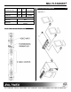
MULTI-TASKER MT103-102 is shown above.
MULTI-TASKER TABLE OF CONTENTS Page PRECAUTIONS / SAFETY WARNINGS ...............2 ABOUT YOUR MT103-102/107.............................3 TECHNICAL SPECIFICATIONS............................3 DESCRIPTION OF MT103-102/107 ......................4 APPLICATION DIAGRAM .....................................4 INSTALLING YOUR MT103-102/107 ....................6 OPERATION .........................................................6 RS-232 CONTROL.............................................6 DESCRIPTION OF COMMANDS ..
MULTI-TASKER PRECAUTIONS / SAFETY WARNINGS These limits are designed to provide reasonable protection against harmful interference when the equipment is operated in a commercial environment. This equipment generates, uses, and can radiate radio frequency energy and, if not installed and used in accordance with the instruction manual, may cause harmful interference to radio communications.
MULTI-TASKER ABOUT YOUR MT103-102/107 2 VGA thru UXGA (MT103-107), RGBHV*& RGBS* Table 1. MT103-102/(107) General see Optional Accessories) MT103-102 & MT103-107 1-in 3-out VGA Distribution Amplifier Card The 1-in 3-out MT VGA DA cards are designed for use in 1 slot of a MultiTasker enclosure. These cards enable the connection of a single computer video source to three monitors or projectors. Resolutions supported range from VGA to UXGA; in the case of the MT103-102, QXGA is supported.
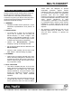
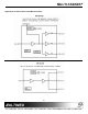
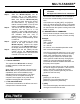
MULTI-TASKER Power (from MT100-100) MT103-102 MT103-107 +6V -6V 250 mA 250 mA 220 mA 220 mA APPLICATION DIAGRAM Power Consumption Application 1 2.8 watts 2.8 watts Optional Accessories 6ft, 15-pin HD Male to 5-BNC Male 6ft, 15-pin HD Male to 5-BNC MS8106CA Female Table 3.
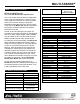
MULTI-TASKER Application 2: Internal View of the MT103-102/107 5
MULTI-TASKER INSTALLING YOUR MT103-102/107 Step 1. Step 2. Step 3. Step 4. 1. Square brackets “[ ]” are part of the command. 2. Use uppercase letters for all commands. After processing a command, an OK or ER string will be returned as feedback if "F" is included at the end of a command string or if the unit ID is zero. 6 Slide the MT103-102/(107) into an available slot in the Multi-Tasker™ Enclosure in order to connect to the bus. Make sure that the MT103-102/(107) card fits into place.
MULTI-TASKER 5. [ON] Command Format: [VERCnUi] This command enables one or more outputs of a single card or group of cards. Cn = card ID number (n = slot # from 1 to 19) (1-8 for MT100-101 or 1-4 for MT100-106) [OnmCnUiS] for a single card Ui = Unit ID (i = # from 0 to 9) (refer to the This command enables output “m” without affecting any other outputs.
MULTI-TASKER Example: executed immediately. The path for outputs on multiple cards or the same card can be loaded. If card 5 of unit 3 has output 1, 2 and 3 ON: Command Format: [ONmCnUiP] a) [OFF1C5U3]: Turns OFF output 1 while output 2 and 3 remain ON. m = output number (m =1 to 3) b) [OFF23C5]: Turns OFF output 2 and 3. Cn = card ID No. (n = a slot # from 1 to 19) (1-8 for MT100-101 or 1-4 for MT100-106) c) [OFFC5U3]: Turns OFF all outputs, which is equivalent to [OFF123C5U3].
MULTI-TASKER [OFF12C6U3P] [OFF34C7U3P] [SW] Gk = group number (k = # from 1-9) Ui = unit number (i = # from 0-9) Example: If "F" is included use the [OFFmCnUiPF] command or the [OFFmCnUiFP] command. To group card #1, 2, and 3 as group 5 of unit #1, send the [WRC1C2C3G5U1] command. After executing this command, card 1, 2, and 3 of group 5 and unit 1 will be grouped together. [OFF...
MULTI-TASKER 7.3 SUMMARY OF COMMANDS member = C1 - C19 (card 1 to 19) (1-8 for MT100-101 or 1-4 for MT100-106) Example: To read member data for group 1 of unit 1, send the [RD] command. The system will return feedback as C1C2C3G5U1. 15. [HELP] This command displays the commands available for the card. Example: To display the commands and their explanations for the card in slot 4, send the following command, [HELPC4]. The feedback will be a listing of the commands along with a brief summary.
MULTI-TASKER TROUBLESHOOTING GUIDE 8 working and there is still no display, see Cause 2. Cause 2: The card output is not selected. Solution: Select the card output. See RS-232 accessible commands in section 7. If no display is present, see Cause 3. Cause 3: Cable connections to the destination are incorrect. Solution: Make sure that cables are connected properly. Also, make sure that the continuity and wiring are good. If there is still no display present, see Cause 4. Cause 4: The display has a problem.