MULTI-TASKER™ MANUAL PART NUMBER: 400-0356-002 MT112-100 24 I/O PORTS, CONTACT CLOSURE/LED DRIVE CONTROL CARD FOR MULTI-TASKER™ USER'S GUIDE
MULTI-TASKER™ TABLE OF CONTENTS Page PRECAUTIONS / SAFETY WARNINGS .............. 2 GENERAL....................................................................2 CLEANING ..................................................................2 FCC / CE NOTICE .......................................................2 ABOUT YOUR MT112-100 ................................... 3 TECHNICAL SPECIFICATIONS .......................... 3 PRODUCT DESCRIPTION ................................... 4 APPLICATION DIAGRAM .........
MULTI-TASKER™ PRECAUTIONS / SAFETY WARNINGS • 1 Please read this manual carefully before using your MT112-100. Keep this manual handy for future reference. These safety instructions are to ensure the long life of your MT112-100 and to prevent fire and shock hazard. 1.1 GENERAL • Qualified ALTINEX service personnel, or their authorized representatives must perform all service on the MT112-100. • To prevent fire or shock, do not expose this unit to rain or moisture.
MULTI-TASKER™ ABOUT YOUR MT112-100 2 TECHNICAL SPECIFICATIONS MT112-100 Universal IO Control Card FEATURES/DESCRIPTION GENERAL Control Ports The MT112-100 has 24 Input/Output ports. These ports are jumper configurable and each may be configured as either an input or an output port. As outputs, these IO ports may be used to control external controls and devices. As inputs, these ports can trigger events and control other cards in the Multi-Tasker™ enclosure.
MULTI-TASKER™ PRODUCT DESCRIPTION 400-0356-002 4 4 4
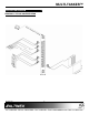
MULTI-TASKER™ APPLICATION DIAGRAM 5 DIAGRAM 1: TYPICAL CONFIGURATION 400-0356-002 5 5
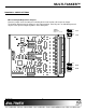
MULTI-TASKER™ DIAGRAM 2: JUMPER SETTINGS P7 U6 C7 R123 K1 P8 C58 C8 C13 INPUT P9 K2 OP1 J8 C35 R65 R42 R67 R33 R36 OP3 R69 U9 OUTPUT INPUT OP2 C11 C1 OP4 K3 R71 OUTPUT OUTPUT INPUT C40 U1 TP8 I G +5v U23 C12 OP9 R81 C39 OP10 R104 R98 C19 OP11 C3 K6 U26 TP9 P19 R102 K7 SLAVE C28 R66 C44 C29 C45 R117 K10 U29 C54 R70 J12 C22 C51 J10 U24 C55 C48 U12 U17 R108 C23 OP21 C43 U16 C53 R110 OP22 C50 R122 R112 R106 R119 C56 C49 C5 U28 R121 C3
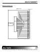
MULTI-TASKER™ DIAGRAM 3: INTERNAL VIEW MT112-100 TERMINAL BLOCK I/O I/O CONTROL MAIN MICRO-PROCESSOR 400-0356-002 7 7 OC 1 OC 2 OC 3 OC 4 OC 5 OC 6 OC 7 OC 8 OC 9 OC 10 OC 11 OC 12 OC 13 OC 14 OC 15 OC 16 OC 17 OC 18 OC 19 OC 20 OC 21 OC 22 OC 23 OC 24
MULTI-TASKER™ INSTALLING YOUR MT112-100 6 1. Step 1. Determine how each port will be used. Either as an Input or as an Output. Set the jumpers accordingly. Square brackets “[ command. 2. Use uppercase letters for all commands. The cards in a Multi-Tasker™ system are capable of performing various functions, as well as providing feedback to the user or control system. Some commands instruct a card to perform specific actions. Other commands request information about the status of the card.
MULTI-TASKER™ The Unit ID has a value from 0 to 9. Unit ID 0 should be used for single unit operation. If the Unit ID is set to 0, then each command can be used without Ui. Use command [SETU0] to set Unit ID 0. See the MT100-100 User’s Guide for more information.
MULTI-TASKER™ [(MT101-101U1)(MT103-122C01) (MT103-123C02)(MT112-100C03)] The I/O port settings are read left to right representing ports one through 24. A “0” indicates the port is low and a “1” indicates the port is high. MT101-101U1 = Panel Number and Unit ID MT103-122C01 = An MT103-122 is in slot 1 MT103-123C02 = An MT103-123 is in slot 2 MT112-100C03 = An MT112-100 is in slot 3 6. [STA1] This command enables automatic feedback from the front panel.
MULTI-TASKER™ [MT112-100 690-0185-003 C04] Check the last three digits against the numbers above to determine if the Card ID commands can address all 99 Card ID's. MT112-100 = model number 690-0185-003 = firmware version C04 = card ID Some cards require more than one slot in the Multi-Tasker™ system. As an example, some matrix switcher cards require 4 slots. If there are 5 of these cards installed, they would be numbered C4, C8, C12, C16 and C20.
MULTI-TASKER™ 12. [SIDnCi] 14. [RSN] This command sets the Card ID of a single card to a number from 1 to 99. This command reads the slot number of the card with a specified ID number, and returns the value to the system to be displayed in the terminal window. If more than one card has the same ID, each slot number will be displayed.
MULTI-TASKER™ Example 1: 18. [WRI] There is an MT112-100 in slot #2. I/O port number "4" is ON. Send the command [RDIO4C2] and the system will return the following feedback: This command assigns a subroutine to perform when there is a transition on an I/O port.
MULTI-TASKER™ Example: The ports are designed to work in pairs. Port 1 handles external Key #1 and Port 2 handles external LED #1. Port 3 handles external Key #2 and Port 4 handles external LED #2. An MT112-100 located in slot #3. Send the command [RDIS*C3] and receive feedback similar to the following: In this setup, the Port 1 jumper should be set to the INPUT position. Port 2's jumper should be in the OUTPUT position and so on. Port01: Sub000, Sub001. Port02: Sub008, Sub009. … Port24: Sub001, Sub020.
MULTI-TASKER™ Command Format: [WRSm=F1,F2,…;CnUi] Example 1: Sm = Subroutine ID (m = # from 1 to 180) F1,F2… = Functions: functions must be separated by a comma. Read back the subroutine in the previous example for the WRS command. The card is in slot #4 and the Subroutine is 2.
MULTI-TASKER™ These subroutines are stored directly on the card and are separate from the commands stored in the Front Panel. Therefore, the front panel LED's cannot be controlled with commands stored on the control card, but they may be used to control other cards.
MULTI-TASKER™ Command Format: [RMGkUi] 33. [CLRG] Gk = Group number (k = # from 1-8) This command clears the members for a single group or for all groups. The clear command restores the cards to default settings and is the equivalent to sending the [CLR] command to each individual card. Ui = Unit ID (i = # from 0-9) Example: Group 5 consists of the cards located in slots number 2, 4 and 6. Remove all cards from the group by sending the command [RMG5].
MULTI-TASKER™ 7.3 SUMMARY of COMMANDS 24) [WRS] Write a subroutine Card Commands 25) [RDS] Read a subroutine 1) [C] Receives card status. 26) [CLRS] Clear a subroutine 2) [CLR] Resets card to default values. 27) [SUB] 3) [TEST] Tests the memory IC's. Execute the functions in a subroutine. 4) [?] Request system information 28) [HELP] Display available commands for the MT112-100. 5) [?Cn] Request card information 6) [STA1] Enable auto feedback. 7) [STA0] Disable auto feedback.
MULTI-TASKER™ WARNING: Do NOT enter any characters except the one relating to the desired menu. Pressing ENTER or RETURN after "8" will force the system back to the original prompt. 7.4.1 MENU COMMAND DEFINITIONS Refer to section 7.2 for details on card functions and examples. SUGGESTION: Before using the menu mode, it is best to disable the automatic feedback feature.
MULTI-TASKER™ MT112-100 MAIN MENU KEY Comments 05 Select MT112-100 in slot #5 1 Select Control Menu and receive the following feedback: 1: CONTROL 2: VERSION 3: STATUS Press Key to Toggle Ports 4: HELP 1:1 (1) 2:2 (1) 3:3 (1) 4:4 (1) 5:5 (1) 6:6 (1) 7:7 (1) 8:8 (1) ESC: GO BACK MT112-100 EXPANDED MENUS 1.
MULTI-TASKER™ TROUBLESHOOTING GUIDE 8 ALTINEX POLICY We have carefully tested and have found no problems in the supplied MT112-100; however, we would like to offer suggestions for the following: 9.1 LIMITED WARRANTY/RETURN POLICY Please see the Altinex website at www.altinex.com for details on warranty and return policy. 8.1 I/O PORT NON RESPONSIVE Cause 1: 9.2 CONTACT INFORMATION Jumpers are not set. ALTINEX, INC Solution 1: The I/O ports may be used as input or output ports.