
User`s guide

MULTI-TASKER™
400-0356-002
8
8
INSTALLING YOUR MT112-100 6
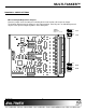
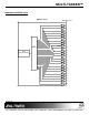
Step 1. Determine how each port will be used.
Either as an Input or as an Output. Set
the jumpers accordingly.
See DIAGRAM 2 for details.
Step 2. Turn off power to the Multi-Tasker™
system.
WARNING: Installing or removing the
MT112-100 while power is
on may result in the loss of
all stored memory
subroutines.
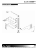
Step 3. Slide the MT112-100 into an available slot
in the MultiTasker™ Basic Enclosure in
order to connect to the bus. Make sure
that the MT112-100 card fits into place.
Secure the card to the MultiTasker™ by
tightening the retainer screws located on
the top and bottom of the MT112-100
card.
Step 4. Turn on power to the Multi-Tasker™
system.
Step 5. Connect control cables as required to the
input/output connector of the MT112-100.
Step 6. Starting from the left, identify the slot
number where the MT112-100 card is
plugged into the Enclosure and note that
it is for RS-232 control.
OPERATION 7
7.1 RS-232 CONTROL
When used in the MultiTasker™ Enclosure, the
MT112-100 has many advanced remote control
capabilities, which are accessible through standard
RS-232 communication. The actual controlling can
be accomplished through a computer control
system or any other device capable of sending
RS-232 commands.
7.1.1 RS-232 INTERFACE
The RS-232 commands for the MT112-100 are
in a simple ASCII character format.
1. Square brackets “[ ]” are part of the
command.
2. Use uppercase letters for all commands.
The cards in a Multi-Tasker™ system are
capable of performing various functions, as well
as providing feedback to the user or control
system. Some commands instruct a card to
perform specific actions. Other commands
request information about the status of the card.
Other commands do both at the same time.
A command that instructs the card to simply
perform an action will generate feedback of “[ ]”.
The open and close brackets indicate the card
received a valid command. If the command
requested information from the card, the
feedback generated by the card is the
acknowledgement of having received a valid
command. Invalid commands generate
feedback of “[ERR001]”.
After processing a command, an OK or
[ERR001] will be returned as feedback if "F" is
included at the end of a command string.
7.2 DESCRIPTION OF COMMANDS
Each command consists of three parts:
Function, Card ID, and Unit ID. [Function, Card
ID, Unit ID]
Example:
[VERC3U2]
VER = Function
C3 = Card ID
U2 = Unit ID
For detailed information regarding Function, see
each command description.
The Card ID is a unique identifier. It is equal to
the enclosure slot number, or it may be an
assigned value. As the slot number, the value
can range from 1 to 4 up to 1 to 20 depending
on the enclosure. If the value is assigned, the ID
may be a maximum of 99. Card ID 0 (C0) is
used for the controller and cannot be
reassigned.