MULTI-TASKER MANUAL PART NUMBER: 400-0092-005 MT104-102 6-IN, 1-OUT VGA SWITCHER TM CARD FOR MULTI-TASKER ENCLOSURES USER’S GUIDE
MULTI-TASKER TABLE OF CONTENTS Page PRECAUTIONS / SAFETY WARNINGS ............... 2 GENERAL.......................................................... 2 INSTALLATION ................................................. 2 CLEANING ........................................................ 2 FCC / CE NOTICE ............................................. 2 ABOUT YOUR MT104-102 ................................... 3 TECHNICAL SPECIFICATIONS ........................... 3 PRODUCT DESCRIPTION .............................
MULTI-TASKER PRECAUTIONS / SAFETY WARNINGS 1 Please read this manual carefully before using your MT104-102. Keep this manual handy for future reference. These safety instructions are to ensure the long life of your MT104-102 and to prevent fire and shock hazard. Please read them carefully and heed all warnings. 1.1 GENERAL • Qualified ALTINEX service personnel, or their authorized representatives must perform all service. • 1.
MULTI-TASKER ABOUT YOUR MT104-102 2 MECHANICAL MT104-102 Enclosure Slots Two Required Weight 1.0 lb (0.45 kg) Connector Panel Black T° Operating 10°C-35°C T° Storage 50°C Humidity 90% non-condensing MTBF (calc.) 40,000 hrs Table 2. MT104-102 Mechanical MT104-102 6-in 1-out MT VGA Switcher Card The MT104-102 6-in 1-out MT VGA SW Card uses two slots in Multi-Tasker enclosures. This card enables multiple computer video sources to be connected and switched to a single scan-rate compatible display.
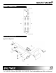
MULTI-TASKER PRODUCT DESCRIPTION 4 APPLICATION DIAGRAM 5 Application Diagram 1 4
MULTI-TASKER Application Diagram 2: Internal View of the MT104-102 5
MULTI-TASKER INSTALLING YOUR MT104-102 After processing a command, an OK or ER will be returned as feedback if "F" is included at the end of a command string or if the unit ID is zero. 6 Step 1. Slide the MT104-102 into an available slot in the Multi-Tasker™ Enclosure in order to connect to the bus. Make sure that the MT104-102 card fits into place. Secure the card to the Multi-Tasker™ by tightening the retainer screws located on the top and bottom of the MT104-102 card.
MULTI-TASKER Example: 3. [ON] This command enables one input of a single card or a group of cards. • [ONmCnUiS]: for a single card If one MT104-102 card is in slot #2 of unit 3: To send command [VERC2U3], the MultiTasker™ Enclosure will return feedback as: This command enables input “m” and disables all other inputs. Default when plugged in = Input 1 is ON m = Input number (m = 1 to 6) Cn = Card ID No.
MULTI-TASKER Example: Example: 1. [OFF1G1U1]: Turns OFF input 1 for each card in group 1 of unit 1. 2. [OFFG1U1]: Turns OFF all inputs for each card in group 1 of unit 1. • [OFF…P]: sets path If there are two MT104-102 cards in slot 6 and 7 of unit 3: To enable input 1 of card 6 and input 3 of card 7 simultaneously, use the following commands: [ON1C6U3P] [ON3C7U3P] [SW] If "F" is included use the [ONmCnUiPF] command or the [ONmCnUiFP] command.
MULTI-TASKER [SW] The system will return feedback as OK if the unit ID is zero. 9. [RD] This command displays the members in each group. Command Format: [RDGkUi] k = group number (k = # from 1-9) i = unit number (i = # from 0-9) member = C1 - C19 (card 1 to 19) (1-8 for MT100-101 or 1-4 for MT100-106) 6. [WR] This command groups multiple cards in the MT100-100 Enclosure. Each unit contains a maximum of nine groups.
MULTI-TASKER TROUBLESHOOTING GUIDE 7.3. SUMMARY OF COMMANDS 1) [VER]: Receives software version 2) [C]: Receives status of the card 3) [ON]: Turns on one input for a single card or a group of cards 4) [OFF]: Turns off one input for a single card or a group of cards 5) [SW]: Switch (activates the preset path) 8 We have carefully tested and have found no problems in the supplied MT104-102; however, we would like to offer suggestions for the following: 8.
MULTI-TASKER Solution 1: Look at the card and verify that source connections are correct. If the source is working and there is still no display, see Cause 2. there is no damage. If there is no damage, see Solution 2. Cause 2: The card input is not selected. Solution 2: Verify that all IC’s are seated in their sockets. If the LED is still blinking red, see Solution 3. Solution: Select the card input. See RS-232 accessible commands in section 7. If no display is present, see Cause 3.