MULTI-TASKER™ MANUAL PART NUMBER: 400-0202-002 MT104-106 3-IN VGA SWITCHER EXPANSION CARD FOR MULTI-TASKER™ USER’S GUIDE
MULTI-TASKER™ TABLE OF CONTENTS Page PRECAUTIONS / SAFETY WARNINGS .............. 2 GENERAL..........................................................2 INSTALLATION..................................................2 CLEANING.........................................................2 FCC / CE NOTICE..............................................2 ABOUT YOUR MT104-106 .................................. 3 TECHNICAL SPECIFICATIONS .......................... 3 PRODUCT DESCRIPTION .................................
MULTI-TASKER™ PRECAUTIONS / SAFETY WARNINGS 1 • This equipment has been tested and found to comply with the limits for a Class A digital device, pursuant to Part 15 of the FCC Rules. These limits are designed to provide reasonable protection against harmful interference when the equipment is operated in a commercial environment.
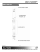
MULTI-TASKER™ ABOUT YOUR MT104-106 2 TECHNICAL SPECIFICATIONS MT104-106 3-In MT VGA Switcher Expansion Card FEATURES/ DESCRIPTION GENERAL Inputs Input Connector Internal Connector The MT104-106 is a 3-In VGA Switcher Expansion Card. It is designed for use together with the MT104-102 or MT104-105 in a Multi-Tasker™ Enclosure. When installed, this card expands the total number of VGA inputs by three. MT104-106 (3) 15-pin HD Female (1) 10-pin IDC VGA thru QXGA, Compatibility RGBHV & RGBS Table 1.
MULTI-TASKER™ PRODUCT DESCRIPTION 400-0202-002 4 4
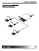
MULTI-TASKER™ APPLICATION DIAGRAMS 5 DIAGRAM 1: TYPICAL CONNECTIONS 400-0202-002 5
MULTI-TASKER™ DIAGRAM 2: INTERNAL VIEW MT104-106 3 IN VGA SW EXPANSION + 350MHZ + POWER LED + PNP .
MULTI-TASKER™ INSTALLING YOUR MT104-106 6 OPERATION 7 Step 1. Turn OFF the enclosure power. 7.1 RS-232 CONTROL Step 2. Locate the VGA card (MT104-102, MT104-105, etc.) to which the internal output cable from the MT104-106 will be connected. Step 3. Remove it from the system. Be careful in case there is another expansion attached to it. When used in the Multi-Tasker™ Enclosure, the MT104-106 has many advanced remote control capabilities, which are accessible through standard RS-232 communication.
MULTI-TASKER™ The Group ID is a number representing a group of cards defined with the [WR] command. When using the Group ID, all cards in the group will perform the given instruction. Example: There is one MT104-106 card in slot #4 with Input 2 ON. Sending the command [C4] to the Multi-Tasker™ will yield the following feedback: Changing the position of a card will significantly affect the commands recorded on software definitions or third party control systems.
MULTI-TASKER™ Example: 6. [STA] A Multi-Tasker™ with Unit ID #0 has a front panel with part number MT101-102 and contains an MT104-106. Send the command [?] and receive the following feedback: This command enables/disables automatic feedback from the front panel. The command affects any card with auto-feedback capability, not just the MT104-106. The default at power on or reset is STA0, OFF.
MULTI-TASKER™ GROUP OPERATION FEEDBACK OPERATION Command Format: [ONmGkUi] Command Format: [ON…..F] This command enables input "m" for each card in group "k" of unit "i". After processing a command, an OK or ER will be returned as feedback if "F" is included at the end of a command string. m = card input (m = # from 1-3) Example: Gk = group number (k = # from 1-8) [ON1C6F]: if path is not set [ON3C7PF]: if path is set Ui = unit number (i = # from 0-9) Example: 8.
MULTI-TASKER™ PATH OPERATION 10. […F] – Feedback Command Format: [OFFmCnUiP] After processing a command, an OK or ER will be returned as feedback if "F" is included at the end of a command string. This command will set the path for the output, but it is not active until the switch command, [SW], is executed. Commands ending in "P" are not executed immediately. The path for outputs on multiple cards or the same card may be preloaded. m 11.
MULTI-TASKER™ The feedback will be a "1" immediately following the command sent: Command Format: [FBDmCnUi] m [SIGC4] 1 [SIGC4] 1 Cn = Card ID (n = # from 1 to max slots) = command sent = feedback, signal is present Ui = Unit ID (i = from 0 to 9) Example: 14. [CLR] The command [HELPC4] is sent to the card in slot #4. Some of the HELP file is displayed on the screen, but most is missing. Send the command [FBD1C4] to slow down the rate at which the card sends feedback to the system.
MULTI-TASKER™ Another use for changing the Card ID is to be able to use multiple systems without having to set each unit to a different Unit ID. All systems may be left as Unit ID 0 for ease of programming. The cards in the first unit may be numbered 1-10 and in the second unit 11-20. Example: Send the command [SID50C10] to set the ID of the card in slot #10 to an ID of 50. 20. [SID+] This command sets the Card ID of all cards in a system to the slot number plus the offset. 17.
MULTI-TASKER™ Example: Example: The card in slot #4 takes up four slots. Its ID was set to 1 since it is the first card installed in the system, reading from left to right. Send the command [RSNC1] to find the slot number. The system responds with the following feedback: To group cards 1, 2, and 3 as group 5 of Unit ID 1, send the command [WRC1C2C3G5U1]. After executing this command, cards 1, 2 and 3 will be grouped together as group 5 of Unit ID 1.
MULTI-TASKER™ Example: 27. [CLRG] Group 1 consists of the cards located in slots number 1, 2 and 3. Remove all cards from the group by sending the command [RMG1]. The system will return the following feedback: This command clears the members for a single group or for all groups. The clear command restores the cards to default settings and is the equivalent to sending the [CLR] command to each individual card. G1=EMPTY Remove all the members from every group, effectively deleting all groups.
MULTI-TASKER™ 7.3 SUMMARY OF COMMANDS 7.4 MENU MODE MENU MODE commands are RS-232 commands that allow virtually the same functionality as programming commands. Unlike the programming commands in the previous sections, 7.2 and 7.3, MENU commands prompt the user to select from a list of available options. The system then responds based upon selections made by the user. Card Commands 1) [VER] Receives software version 2) [Ci] Receives status of the card 3) [CnS] Saves card configuration.
MULTI-TASKER™ 8. 7.4.2 USING MENU MODE SUGGESTION: Before using the menu mode, it is best to disable the automatic feedback feature. The values and current settings will be displayed in the menu mode, but the automatic feature will display after each setting change making the menus difficult to read. 1. In order to enter MENU mode, the system needs to be connected to a computer running MTSetup™ or other RS-232 control software. 2.
MULTI-TASKER™ MT104-106 EXPANDED MENUS 1.
MULTI-TASKER™ 7.4.5 MENU MODE EXAMPLES 4. Display Card Status All MENU MODE examples assume an MT104-106 is installed in slot #4. Start by clicking the mouse in the Terminal window. Press ENTER and a list of available cards will be displayed. Starting from the Main Menu, follow the keystrokes below. 3 Displays card status NOTE: The status will be displayed, followed by the Main Menu being redisplayed. 1. Select An Input Follow the keystrokes below to select Input 3 as the source input.
MULTI-TASKER™ 8.2 LED IS BLINKING RED Cause 1: The CPU on the card is not working properly. Solution 1: Look at the card and verify that there is no damage. If there is no damage, see Solution 2. 9.2 CONTACT INFORMATION ALTINEX, INC 592 Apollo Street RS485 communication error Brea, CA 92821 USA Solution 1: Make sure that the card is pushed all the way into the slot. If there is still an error, see Solution 2. TEL: 714 990-2300 TOLL FREE: 1-800-ALTINEX WEB: www.altinex.