
User`s guide


MULTI-TASKER™
400-0202-002 7
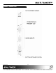
INSTALLING YOUR MT104-106 6
Step 1. Turn OFF the enclosure power.
Step 2. Locate the VGA card (MT104-102,
MT104-105, etc.) to which the internal
output cable from the MT104-106 will
be connected.
Step 3. Remove it from the system. Be careful
in case there is another expansion
attached to it.
Step 4. Connect the 10-pin connector of the
MT104-102 to the 10-pin connector
located on the MT104-106 using the
10-pin IDC cable provided.
Step 5. Slide the (previously connected)
MT104-102 and the MT104-106 into
available slots in the Multi-Tasker™
Enclosure. Make sure that the
MT104-106 and the MT104-102 fit into
place.
Step 6. Secure the cards to the Multi-Tasker™
by tightening the retainer screws
located on the top and bottom of each
card.
Step 7. Turn the system power ON. The LED
on the MT104-106 should be ON and
RED. The LED will turn GREEN if a
valid signal is applied.
Step 8. Connect an output cable from the video
source to the input connector of the
MT104-106. The POWER/SIGNAL LED
should turn GREEN.
Step 9. Connect the output connector of the
MT104-102 to the display.
Step 10. Starting from the left, count the slot
number of the MT100-100 where the
MT104-106 is plugged into the
Enclosure and note that it is for the
Card ID as used with RS-232 control.
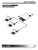
OPERATION 7
7.1 RS-232 CONTROL
When used in the Multi-Tasker™ Enclosure, the
MT104-106 has many advanced remote control
capabilities, which are accessible through standard
RS-232 communication. The actual controlling can
be accomplished through a computer control
system or any other device capable of sending
RS-232 commands.
7.1.1 RS-232 INTERFACE
The RS-232 commands, for the MT104-106 are
in a simple ASCII character format.
1. Square brackets “[ ]” are part of the
command.
2. Use uppercase letters for all commands.
After processing a command, an OK or ER will
be returned as feedback if "F" is included at the
end of a command string.
Commands ending in "S" will be saved into
memory. Commands not ending in "S" will still
be executed but will not be restored when the
system is reset or powered OFF then ON.
7.2 DESCRIPTION OF COMMANDS
Each command consists of three parts:
Function, Card ID, and Unit ID.
[ Function , Card ID , Unit ID ]
Example: [VERC3U2]
VER = Function
C3 = Card ID or Group ID
U2 = Unit ID
For Function, see a detailed explanation under
each command description.
The Card ID is an assigned value. It is equal to
the enclosure slot number in which the card is
installed. The value can range from 1 to 4 up to
1 to 20 depending on the enclosure.
Card ID 0 (C0) is used for the controller. See
the MT100-100 User’s Guide for details.