
User`s guide


MULTI-TASKER™
400-0351-003 11
Command Format: [VERCnUi]
Cn = Card ID (n = slot # from 1 to max slots)
Ui = Unit ID (i = # from 0 to 9)
Example:
There is an MT107-100 card is in slot #5. Send
the command [VERC5] and the Multi-Tasker™
will return feedback as:
[ MT107-100 690-0159-004 C05]
MT107-100 = the card model
690-0159-004 = the software version
C05 = card ID number
5. [MAT]
This command sets the matrix configuration for
the matrix engine.
Command Format:
[MATj;mm;ww;xx;yy;kk;ll;CnUiS]
j = Matrix ID (j = # from 1 to 9)
The following properties MUST be entered in
two (2) digit format.
mm = Inputs (2 digit # from 01-64)
zz = Outputs (2 digit # from 01-64)
xx = Input Offset (2 digit # from 00-99)
yy = Output Offset (2 digit # from 00-99
kk = Channel Width (2 digit # from 01-32)
ll = Channel Spacing (2 digit # from 00-31)
Cn = Engine Card Slot Number
(The slot number of the LEFT card of the
engine is the Engine Card Slot number.)
Ui = Unit ID (i = # from 0 to 9)
S = Save
This property saves the configuration to
Matrix ID memory and will allow the
configuration to be recalled any time,
even after power up or reset.
Adding the 'S' to the command will also
make the matrix configuration the default
at power up. The last configuration ID
created and saved will be the default at
power up.
In order to change the power up default
without having to redefine the settings,
see the command [MjCnS].
Matrix Configuration Definitions:
1. Matrix ID: A total of 9 matrix configurations
may be defined in a single engine. Once
saved, the configuration may be recalled by
number without having to redefine the
settings.
2. Number of Inputs: The number of inputs in
the configuration, or eight times the number
of input cards installed is the maximum.
If the channel width and spacing are
different, then the number of inputs will be
lower. For example, in a 32X32 matrix with
a width of 4 and a spacing of 7, the number
of inputs would be 8. See Example 1 in this
section for specifics.
3. Number of Outputs: Same as for Inputs.
4. Input Offset: The offset defines where Input
#1 will be in reference to Input #1 on the
Input Connector Card. Typically, Input #1
would be Input #1 of the base card.
However, an offset of 8 will make Input #1
start at the actual Input #9.
5. Output Offset: Same as for Input Offset.
6. Channel Width: The number of signals per
channel. The default width is one.
7. Channel Spacing: The default spacing is
zero. When dealing with multi-cabled
signals, the spacing is typically one less
than the number of inputs on a single card.
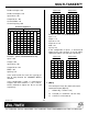
Matrix Assembly Layout:
Input cards count from the main Input
Connector Card, RIGHT to LEFT.
Output cards count from the main Output
Connector Card, LEFT to RIGHT.
The following table illustrates the card and
channel numbering. The channel numbering is
based upon the default configuration. The
default configuration is configured as a 64X64
Matrix with the following settings: