MULTI-TASKER™ MANUAL PART NUMBER: 400-0343-003 MT109-102 3 IN 1 OUT AUDIO/MIC MIXER FOR MULTI-TASKER™ USER’S GUIDE
MULTI-TASKER™ TABLE OF CONTENTS Page PRECAUTIONS / SAFETY WARNINGS .............. 2 GENERAL..........................................................2 CLEANING.........................................................2 FCC / CE NOTICE..............................................2 ABOUT YOUR MT109-102 .................................. 3 TECHNICAL SPECIFICATIONS .......................... 3 DESCRIPTION OF MT109-102 ............................ 4 APPLICATION DIAGRAM ....................................
MULTI-TASKER™ PRECAUTIONS / SAFETY WARNINGS ....... 1 • This equipment has been tested and found to comply with the limits for a Class A digital device, pursuant to Part 15 of the FCC Rules. These limits are designed to provide reasonable protection against harmful interference when the equipment is operated in a commercial environment.
MULTI-TASKER™ ABOUT YOUR MT109-102 2 TECHNICAL SPECIFICATIONS MT109-102 3 in 1 out Audio Mixer Card FEATURES/DESCRIPTION GENERAL Inputs Input Connectors The MT109-102 is a Stereo Audio Mixer Card. When installed in the Basic Enclosure (MT100-100), this card allows connection of up to three line level balanced or unbalanced microphone inputs.
MULTI-TASKER™ DESCRIPTION OF MT109-102 400-0343-003 4 4 4
MULTI-TASKER™ APPLICATION DIAGRAM 5 DIAGRAM 1: TYPICAL SETUP 400-0343-003 5 5
MULTI-TASKER™ DIAGRAM 2: INTERNAL VIEW AUDIO INPUTS TB PHANTOM POWER MP CONTROL AUDIO OUTPUT POWER SUPPLY SW5 M+ SW4 M- MIC LINE/MIC INPUT1 BALANCED SW1 S/W GAIN VOLUME BASS TREBLE SW7 M+ SW6 M- MIC SW2 LINE/MIC INPUT2 BALANCED S/W GAIN Σ SW9 M+ SW8 M- MIC LINE/MIC INPUT3 BALANCED 400-0343-003 SW3 S/W GAIN 6 6 SW10 S/W GAIN FIXED MIX LINE LEVEL OUTPUT OR ADJUSTABLE MIX LINE LEVEL OUTPUT TERMINAL BLOCK
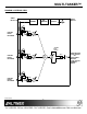
MULTI-TASKER™ DIAGRAM 3: SWITCH POSITIONS INPUT1 INPUT2 PHANTOM POWER LINE MIC ON OFF INPUT3 PHANTOM POWER LINE MIC - + - + OFF ON LINE OUTPUT PHANTOM POWER LINE MIC - + - + ON OFF FIX ADJ - + - + SW1 OFF ON SW2 OFF ON SW3 SW4 SW5 SW6 SW7 OFF ON ON OFF ON OFF ON OFF ON SW8 ON SW9 OFF ON OFF OFF SW10 400-0343-003 OFF 7 7 ON
MULTI-TASKER™ INSTALLING YOUR MT109-102 6 OPERATION Step 1. Turn off the power to the Multi-Tasker™ enclosure. 7 7.1 RS-232 CONTROL When used in the Multi-Tasker™ Enclosure, the MT109-102 has many advanced remote control capabilities, which are accessible through standard RS-232 communication. The actual controlling can be accomplished through a computer control system or any other device capable of sending RS-232 commands. Step 2.
MULTI-TASKER™ The Group ID is a number representing a group of cards defined with the [WR] command. When using the Group ID, all cards in the group will perform the given instruction. Example: There is one MT109-102 card in slot #4. Sending the command [C4] to the Multi-Tasker™ will display feedback similar to the following: Changing the position of a card will significantly affect the commands recorded on software definitions or third party control systems.
MULTI-TASKER™ 4. [?CnUi] 5. [?Ui] This command will return general information about the card and its status. It is a function of both the card and the front panel and is only available with Multi-Tasker™ Front Panel systems that have the following firmware: 690-0122-015 690-0123-004 690-0124-018 This command will return general information about the Multi-Tasker™ and cards installed in the unit. Command Format: [?Ui] Cn = Card ID (n = # from 1 to max slots) = Version 015 or later.
MULTI-TASKER™ Command Format: [SELImCnUi] 7. […S] – SAVE m This command will save the configuration command being sent in memory. When sending the command [VLBA12C4S], after reset or power up, the bass level on C4 will be 12 out of 16. Cn = Card ID (n = slot # from 1 to max slots) Ui = Unit ID (i = # from 0 to 9) Example: 8. […F] – FEEDBACK An MT109-102 is in slot #4. Adjust the volume on Input 2 by sending the command [SELI2C4] and then using the [+] and [-] commands.
MULTI-TASKER™ Example: Example: An MT109-102 is in slot #4. Adjust the BASS on the output by sending the command [SELBC4] and then using the [+] and [-] commands. Set Input 2 volume level to a value of 8 for the card in slot #4. Send the command [VLI2A8C4]. 16. [VLBA] 13. [SELT] This command sets the path to adjust the treble level. The TREBLE level range is 00 to 16 and is adjustable using the [+] and [-] commands. This command sets the output BASS level to an absolute level.
MULTI-TASKER™ When defined as a volume control key, the key will respond to two conditions: press and release. Below, subroutine 8 starts ramping up when key 8 is pressed and subroutine 10 starts ramping down when key 10 is pressed. Subroutine 108 stops ramping when either key is released. 19. [LOD1] This command enables the loudness feature.
MULTI-TASKER™ Example: 25. [RST] Ramp the output volume from a starting level of 1 to a level of 10 for the card in slot #8. Send the command [RUP=10C8] and the system will respond with the following feedback: This command stops ramping and maintains the last volume setting. Command Format: [RSTCnUi] Cn = Card ID (n = # from 1 to max slots) [02][03][04]…[10] Ui = Unit ID (i = # from 0 to 9) 23.
MULTI-TASKER™ Command Format: [RAMP=xCnUi] 29. [FBD] x = Rate in Seconds 4 = 0.25 seconds/step 6 = 0.38 seconds /step 8 = 0.50 seconds /step 10 = 0.63 seconds /step 12 = 0.75 seconds /step 14 = 0.88 seconds /step 16 = 1.00 seconds /step 18 = 1.13 seconds /step Cn = Card ID (n = # from 1 to max slots) Ui = Unit ID (i = # from 0 to 9) This command turns feedback delay on or off. It is necessary when installing some newer cards in older systems.
MULTI-TASKER™ Some cards require more than one slot in the Multi-Tasker™ system. As an example, some matrix switcher cards require 4 slots. If there are 5 of these cards installed, they would be numbered C4, C8, C12, C16 and C20. Changing the Card ID allows the user to define the cards as C1, C2, C3, C4 and C5. 32. [SIDnCi] This command sets the Card ID of a single card to a number from 1 to 99.
MULTI-TASKER™ If assigning group commands to button functions, it is best to use the "Press and Hold on Power Up" to make group settings. 34. [RSN] This command reads the slot number of the card with a specified ID number, and returns the value to the system to be displayed in the terminal window. If more than one card has the same ID, each slot number will be displayed.
MULTI-TASKER™ The cards in slots 1, 2 and 19 are part of group 5. Read the member data for group 5, by sending the command [RDG5]. The system will return feedback as follows: 38. [RMG] This command may be used to delete an entire group, or all groups. REMOVE ONE GROUP MEMBERS G1=C1C2C19 Remove all the members from the group, effectively deleting the group. The feedback shows G1 (Group 1) and then the cards that make up Group 1. In this case, Group 1 includes C1, C2 and C19.
MULTI-TASKER™ Example: 18) [LOD0] Turn ON loudness feature Group 5 of Unit ID 1 contains the cards in slots 1, 2 and 19. Read the member data for group 5 of Unit ID 1. Send the command [RDG5U1] and receive the following feedback: 19) [LOD1] Turn OFF loudness feature 20) [CLR] Reset card to default values 21) [RUP] Ramp volume UP to max (16) G1=C1C2C19 22) [RUP=] Ramp volume UP to a value Now, clear group 5 by sending the command [CLMG5U1].
MULTI-TASKER™ MENU Control Select Save Clear Volume Loudness Mute Setup Group Input Volume Ramp Time Status Help 7.4 MENU MODE MENU MODE commands are RS-232 commands that allow virtually the same functionality as programming commands. Unlike the programming commands in the previous sections, 7.2 and 7.3, MENU commands prompt the user to select from a list of available options. The system then responds based upon selections made by the user.
MULTI-TASKER™ Example: 08 (Slot 8): MT109-102 7.4.4 MT109-102 MENUS NOTE: Only cards supporting the MENU feature will be displayed. 5. 6. Following are the menus available to the MT109-102. The first menu is the Main Menu only. The second listing is an expansion of all the menu items available. Find the alphanumeric characters representing the card whose setup requires changing. It will be the first one or two characters in the line.
MULTI-TASKER™ MT109-102 EXPANDED MENUS 1.
MULTI-TASKER™ 3: SET RAMP TIME 1. Select THIS CARD for control CURRENT RAMP TIME: 18 SEC Follow the keystrokes below to select Input 3 as the source input. 1: 04 SEC 2: 06 SEC 3: 08 SEC 4: 10 SEC 5: 12 SEC 6: 14 SEC 7: 16 SEC 8: 18 SEC Enter 01 1 1 0 ESC ESC List available cards Select MT109-102 in slot #1 Select CONTROL Menu Select Card/Group Select Select This Card (card #1) Return to CONTROL Menu Return to the MAIN Menu ESC: GO BACK 2.
MULTI-TASKER™ Solution 2: Take any other known good card with an LED and verify that the slot used is good by seeing if the other card’s LED lights in that slot. If it lights, then the original card may be the source of the problem. Call ALTINEX at (714) 990-2300. 4. Set Ramp Time Starting from the main menu, set the ramp time to 10 seconds. Follow the keystrokes below. 2 3 4 ESC ESC Select SETUP Menu Select Set Ramp Time Select Ramp Time = 10 seconds Return to SETUP menu Return to the MAIN Menu 8.
MULTI-TASKER™ 8.3 SOUND DISTORTION Cause 1: ALTINEX POLICY Source level is above 0.7Vp-p. 9.1 LIMITED WARRANTY/RETURN POLICY Solution1: Make sure that the source level is below 1V p-p. If the sound is still distorted, see Solution 2. Please see the Altinex website at www.altinex.com for details on warranty and return policy. Solution 2: Call ALTINEX at (714) 990-2300. 9.2 CONTACT INFORMATION 8.4 SOUND LEVEL IS LOW Cause 1: ALTINEX, INC Volume levels are inappropriate.