SPECIAL APPLICATION MANUAL PART NUMBER: 400-0384-002 PE1005 CONTROL CARD FOR PIONEER PLASMA DISPLAY USER’S GUIDE
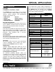
SPECIAL APPLICATION TABLE OF CONTENTS Page PRECAUTIONS / SAFETY WARNINGS ............... 2 GENERAL..........................................................2 INSTALLATION .................................................2 CLEANING.........................................................2 HANDLING ........................................................2 FCC / CE NOTICE..............................................2 ABOUT YOUR PE1005............................................. 3 TECHNICAL SPECIFICATIONS ...
SPECIAL APPLICATION PRECAUTIONS / SAFETY WARNINGS 1.5 FCC / CE NOTICE 1 Please read this manual carefully before using your PE1005. Keep this manual handy for future reference. These safety instructions are to ensure the long life of your PE1005 and to prevent fire and shock hazard. Please read them carefully and heed all warnings. • 1.1 GENERAL • • There are no user serviceable parts on this unit. Qualified ALTINEX service personnel must perform all service on the PE1005. 1.
SPECIAL APPLICATION ABOUT YOUR PE1005 The HelpInside™ feature allows programmers to have access to command structures and control of the PE1005 from any terminal. This technology provides easier than ever control of the PE1005 with simple keyboard commands. 2 PE1005 PIONEER CONTROL CARD The PE1005 Pioneer card allows users to control events on Pioneer Plasma displays using many different control protocols and programmed functions.
SPECIAL APPLICATION DESCRIPTION OF PE1005 4 25-PIN D-SUB USB CONNECTOR APPLICATION DIAGRAMS RJ-45 NETWORK JACK CONNECTOR TCP/IP DIGITAL I/O 5 DIAGRAM 1: TYPICAL SETUP 400-0384-002 4
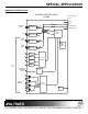
SPECIAL APPLICATION DIAGRAM 2: INTERNAL VIEW PIONEER CONTROL CARD PE1005 EDGE CONNECTOR PE 1005 TX TX PDP RX PDP ETHERNET RJ-45 ETHERNET TRANSCEIVER TX RX VIDEO CARD TX USB TX/RX RC-232 TX/RX RS485 USB TRANSCEIVER TX RS-232 to TTL TX RS485 TRANSCEIVER 11 OC 12 OC 13 OC 14 OC D-SUB 25 PIN MONITOR DETECTOR INPUT TX MAIN MP REAL TIME CLOCK TX INPUT CONTROL ADC 1 2 CONTACT RELAYS 3 RELAY CONTROL POWER 4 400-0384-002 5 TX VIDEO CARD
SPECIAL APPLICATION DIAGRAM 3: CARD DETAILS P3 Test Connector Used for circuit card evaluation. LED1 SW1 RS-232/RS-485 selection. The RS-232 position is shown. BATTERY 3V Lithium CR1225 400-0384-002 P5 Test Connector Used for circuit card evaluation.
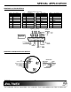
SPECIAL APPLICATION DIAGRAM 4: 25 PIN HD DETAILS DB25 Female Connector PIN 1 2 3 4 Description Input 1 Input 2 Input 3 Input 4 PIN Description PIN 5 6 7 8 9 10 11 12 Relay 1 Throw Relay 1 Pole Relay 2 Throw Relay 2 Pole Relay 3 Throw Relay 3 Pole Relay 4 Throw Relay 4 Pole 13 14 15 16 17 18 19 20 Description 9 8 7 6 5 21 22 23 24 25 21 22 Motion Det. + Motion Det. Trg. GND GND GND Motion Det. + Motion Det. Trg.
SPECIAL APPLICATION 6 3. Step 2. Use ESD safety precautions and always wear a ground strap when handling the PE1005. Check for a “readme” file that may contain special installation instructions. If there is a “readme” file, print and read the contents prior to running the application. 4. Launch the application. 5. Follow the instructions provided by the installation wizard. 6. Connect the PE1005 to the computer’s USB port. The unit should be operational.
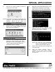
SPECIAL APPLICATION 6. Click on the “Search” button to check for new devices on the LAN. 9. When the command window appears, press ENTER when prompted to enter Setup Mode and then select the factory defaults. 10. Next, select “Channel 1 Configuration”. 11. View each line item as it appears. Press ENTER to leave the default value, or enter the new value and press ENTER. NOTE: If you want to assign the IP manually, click “Assign IP”.
SPECIAL APPLICATION OPERATION 1. [STATUS] 7 This command displays the status of the PE1005 and includes input status, relay settings, assigned subroutines and alarm information. Command Format: [STATUSCi] 7.1 RS-232 CONTROL The PE1005 has many advanced remote control capabilities, which are accessible through standard RS-232 communication. Actual controlling may be achieved using a computer control system or other device capable of sending RS-232 commands. Ci = Card ID (i = # from 1 to 99) 7.1.
SPECIAL APPLICATION Example: 5. [WAIT] Reset the PE1005 with unit ID 1 to its default settings by sending the command [FRESETC1]. The card will display a notice that a reset is in process: PLEASE WAIT CARD IS PERFORMING FACTORY RESET This command will cause the card to suspend operation for specified period, up to ten seconds. If several commands are present in a single subroutine, use this command to make a pause in between each command if desired.
SPECIAL APPLICATION 7. [RDRL] 9. [WRRLk=x] This command is used to read the status of one or all of the internal relays. A ‘1’ indicates the relay is on or closed. A ‘0’ indicates the relay is off or open. The internal relays have a maximum current capacity of 1A and 100VDC. Command Format: [RDRLnCi] This command is used to set one or all internal relays on or off. A ‘1’ will close the relay and a ‘0’ will open a relay. The internal relays have a maximum current capacity of 1A and 100VDC.
SPECIAL APPLICATION Example: Now, send the command [RDS10] to read the contents of subroutine 10. The feedback will be as follows: SUB10/NONE/: WRRL1=1,WAIT10,WRRL1=0, SET1ALARM30800,ALRMON1 13. [WRLS] Subroutine 10 is assigned to Input #1, subroutine 20 is assigned to Input #2, subroutine 30 is assigned to Input #3, and subroutine 40 is assigned to Input #4. Send the command [RDIN*] and receive the following feedback: IN#1=SUB10 IN#2=SUB20 IN#3=SUB30 IN#4=SUB40 12.
SPECIAL APPLICATION Clear the label for subroutine 50 by sending the command [CLRLS50]. After sending this command, reading the contents of subroutine 50 will be as follows: SUB50/NONE/: WRRL*=0 18. [SUB] 15. [RDLS] This command displays the subroutine label of one or all subroutine memory locations. Command Format: [RDLSmCi] m = Subroutine (m = # from 1 to 99, * for all) Ci = Unit ID (i = # from 1 to 99) Example: This command executes the functions stored in a subroutine.
SPECIAL APPLICATION [SETTIME073000] [RDTIME] The display will be similar to the following: TIME: 07:30:05 21. [SETDAY] 23. [RDTIME] This command reads back the time from internal clock. Command Format: [RDTIMECi] This command is used to program the internal clock with the day of the week.
SPECIAL APPLICATION Mode 1 Mode 2 Mode 3 Mode 4 Mode 5 = = = = = Every Minute Every Hour Every Day Every Month Every Week Alarm #1 is now enabled and running. Every minute when the second count matches “30”, the functions stored in subroutine 10 will be executed. If the time is 10:00:00AM, the alarm will trigger at the following times: 10:00:30 10:01:30 10:01:30 … 27. [SET1ALRM2] – MODE 2 - Every Hour The following is required for the alarm to function: 1. Set the Time, Day and Date on the PE1005. 2.
SPECIAL APPLICATION Example: w Associate Alarm #1 with subroutine 10 and set Alarm #1 to trigger at 12 noon every day by sending the following commands: [ALRM1=SUB10] [SET1ALRM3120000] [ALRMON1] Alarm #1 is now enabled and running. Every day at noon, the functions stored in subroutine 10 will be executed. 29.
SPECIAL APPLICATION The alarm functions that follow are used to setup the alarms and enable and disable the alarms. The examples used in the next commands reference subroutine 10 and assume the time and date are already set. Subroutine 10 is programmed to close internal relay number one, wait a half-second and then open the relay. [ALRM2=SUB10] [SET2ALRM230] [ALRMON2] Alarm #2 is now enabled and running.
SPECIAL APPLICATION Example: ALARM CONTROLS Associate Alarm #2 with subroutine 10 and set Alarm #2 to trigger at 2:30PM on the 15th day of the month by sending the following commands: [ALRM2=SUB10] [SET2ALRM4143015] [ALRMON2] Alarm #1 is now enabled and running. Every month on the 15th at 2:30PM, the functions stored in subroutine 10 will be executed. 35. [SET2ALRM5] – MODE 5 - Once A Week 36. [ALRMON] This command activates Alarm #1 and Alarm #2.
SPECIAL APPLICATION Example: 39. [ALRMn=SUBk] Program RS memory location 50 with the string “STANDBY_ON” by sending the command [WRM50=STANDBY_ON;1]. Using the ‘1’ option, this will overwrite whatever information is currently in location 50 and save the command “STANDBY_ON”. 41. [WRLM] This command sets the dependencies between an alarm and a subroutine. The functions in the subroutine will be executed when the alarm conditions are met.
SPECIAL APPLICATION Example: 43. [RDLM] Clear the contents of all RS-232 memory location labels by sending the command [CLRLM*]. The PE1005 will respond with “OK” when the labels are cleared. This command displays the data for one or all memory location labels. Command Format: [RDLMmCi] m = Memory Location (m = 1 to 99, * for all) Ci = Unit ID (i = # from 1 to 99) Example: COMMUNICATION The next several commands deal with internal and external communication.
SPECIAL APPLICATION Command Format: [OUTVCMmCi] 48. [OUTRSM] This command sends the contents of an RS memory location to the external RS-232 port. Command Format: [OUTRSMmCi] m = Memory Location (m = # from 1 to 99) Ci = Unit ID (i = # from 1 to 99) Example: m = Memory Location (m = # from 1 to 99) Ci = Unit ID (i = # from 1 to 99) Example: Send the contents of RS memory location 1 to the internal bus to the Video card by sending the command [OUTVCM1].
SPECIAL APPLICATION 54. [SENDPS] 57. [MDOFF] This command sends data directly through the internal RS-232 bus to the main control card. The data between the “< >”s is sent to the bus. Command Format: [SENDPSCi] This command is used to deactivate/disable the motion detector. Command Format: [MDOFFCi] Ci = Unit ID (i = # from 1 to 99) Example: xxx = ASCII Characters (16 maximum) Ci = Unit ID (i = # from 1 to 99) Example: Send the string “INPUT” by sending the following command, [SENDPS]. 55.
SPECIAL APPLICATION Command Format: [SETMD=xCi] Command Format: [MDTYPE=xCi] x x = Trigger Level (x = # from 01 to 50) 01 = 0.1V 02 = 0.2V … 50 = 5.0V Ci = Unit ID (i = # from 1 to 99) Example: = Sensor Type (x = 0 or 1) 0 = Ultrasound Motion Detector 1 = PIR Motion Detector Ci = Unit ID (i = # from 1 to 99) Example: Set the time delay to a value of one minute by sending the command [SETTMD=10]. Use the [RDMD] command to read values and check settings. 63. [RDMD] Set the trigger level a value of 1.
SPECIAL APPLICATION REMEMBER: A command sent without the unit ID will be executed by all the PE1005’s connected to the RS-232 port. 65. [SIDn] 7.3 SUMMARY OF COMMANDS 1) [STATUS] Display status of the card. 2) [FRESET] Perform factory reset. 3) [VER] Display card information. This command sets the ID number of all cards connected to the RS-232 bus to the same value. The default unit ID is zero. Command Format: [SIDn] 4) [TEST] Test memory IC's. 5) [WAIT] Suspend operation.
SPECIAL APPLICATION 36) [ALRMON] Activate Alarm. 7.4 PLASMA CONTROL WITH INTERNAL BUS 37) [ALRMOFF] Deactivate Alarm. 38) [RDALRM] Read alarm settings. The PE1005 has the capability of sending commands directly to the plasma’s internal bus or to third party video cards installed in the plasma. This allows the user to control settings on the display without having to use the menu buttons on the display or with the remote control. 39) [ALRMn=SUBk] Set Alarm Dependencies. 40) [WRM] Save RS-232 data.
SPECIAL APPLICATION Example 1: Adjustment Mode Place the plasma into adjustment mode by sending the following command directly to the internal bus: [SENDBS<%02%2A%2AAJY%03>] Pioneer website: www.pioneerelectronics.com Example 2: Adjust Brightness Now that the plasma is in adjustment mode, various settings may be changed.
SPECIAL APPLICATION 8.3 INPUT PORTS DO NOT RESPOND Cause 1: Solution: Cause 2: Solution: 400-0384-002 ALTINEX POLICY The input pin is not grounded. Short the input port to ground using a switch or other device. Then send the command [RDI*]. The status of all input ports will be read and displayed. A ‘1’ is for high and a ‘0’ is for a low. Verify the pin that is grounded reads a low, ‘0’. If all the ports show a high, ‘1’, call ALTINEX at (714) 990-2300. Otherwise, see Cause 2.