SPECIAL APPLICATION MANUAL PART NUMBER: 400-0384-003 PE1005 CONTROL CARD FOR PIONEER PLASMA DISPLAY USER’S GUIDE
SPECIAL APPLICATION TABLE OF CONTENTS Page PRECAUTIONS / SAFETY WARNINGS................ 2 GENERAL..........................................................2 INSTALLATION..................................................2 CLEANING.........................................................2 HANDLING ........................................................2 FCC NOTICE .....................................................2 ABOUT YOUR PE1005.............................................
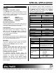
SPECIAL APPLICATION PRECAUTIONS / SAFETY WARNINGS 1.5 FCC NOTICE 1 Please read this manual carefully before using your PE1005. Keep this manual handy for future reference. These safety instructions are to ensure the long life of your PE1005 and to prevent fire and shock hazards. Please read them carefully and heed all warnings. • 1.1 GENERAL • • There are no user-serviceable parts on this unit. Qualified ALTINEX service personnel must perform all service on the PE1005. 1.
SPECIAL APPLICATION ABOUT YOUR PE1005 The HelpInside feature allows programmers to have access to command structures and control of the PE1005 from any terminal. This technology provides easier-than-ever control of the PE1005 with simple keyboard commands. 2 PE1005 PIONEER CONTROL CARD The PE1005 Pioneer Control card allows users to control events on Pioneer Plasma displays using many different control protocols and programmed functions.
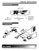
SPECIAL APPLICATION DESCRIPTION OF PE1005 4 25-PIN D-SUB USB CONNECTOR APPLICATION DIAGRAMS RJ-45 NETWORK JACK CONNECTOR TCP/IP DIGITAL I/O 5 DIAGRAM 1: TYPICAL SETUP 400-0384-003 4
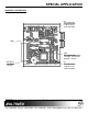
SPECIAL APPLICATION DIAGRAM 2: INTERNAL VIEW PIONEER CONTROL CARD PE1005 EDGE CONNECTOR PE 1005 TX TX PDP RX PDP ETHERNET RJ-45 ETHERNET TRANSCEIVER TX RX VIDEO CARD TX USB TX/RX RC-232 TX/RX RS485 USB TRANSCEIVER TX RS-232 to TTL TX RS485 TRANSCEIVER 11 OC 12 OC 13 OC 14 OC D-SUB 25 PIN MONITOR DETECTOR INPUT TX MAIN MP REAL TIME CLOCK TX INPUT CONTROL ADC 1 2 CONTACT RELAYS 3 RELAY CONTROL POWER 4 400-0384-003 5 TX VIDEO CARD
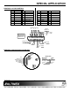
SPECIAL APPLICATION DIAGRAM 3: CARD DETAILS P3 Test connector used for circuit card evaluation. LED1 SW1 RS-232/RS-485 selection. The RS-232 position is shown. BATTERY 3V Lithium CR1225 400-0384-003 P5 Test connector used for circuit card evaluation.
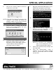
SPECIAL APPLICATION DIAGRAM 4: 25-PIN HD DETAILS PIN Description PIN 1 Input 1 Description PIN 5 Relay 1 Throw 13 GND Description 21 Motion Det. + 2 3 4 Input 2 Input 3 Input 4 6 7 8 9 10 11 12 Relay 1 Pole Relay 2 Throw Relay 2 Pole Relay 3 Throw Relay 3 Pole Relay 4 Throw Relay 4 Pole 14 15 16 17 18 19 20 RS-232 TX GND RS-232 RX GND RS-485+ RS-485 GND 22 23 24 25 Motion Det. Trg.
SPECIAL APPLICATION INSTALLING YOUR PE1005 6 3. Check for a “readme” file that may contain special installation instructions. If there is a “readme” file, print and read the contents prior to running the application. 4. Launch the application. 5. Follow the instructions provided by the Installation Wizard. 6. Connect the PE1005 to the computer’s USB port. The unit should be operational. If not, it may be necessary to reboot the computer. Step 1. Turn off the power to the plasma display. Step 2.
SPECIAL APPLICATION 6. Click on the “Search” button to check for new devices on the LAN. 9. When the command window appears, press ENTER when prompted to enter Setup Mode and then select the factory defaults. 10. Next, select “Channel 1 Configuration”. 11. View each line item as it appears. Press ENTER to leave the default value, or enter the new value and press ENTER. NOTE: If you want to assign the IP manually, click “Assign IP”.
SPECIAL APPLICATION OPERATION 1. [STATUS] 7 This command displays the status of the PE1005 and includes input status, relay settings, assigned subroutines, and alarm information. 7.1 RS-232 CONTROL The PE1005 has many advanced remote control capabilities, which are accessible through standard RS-232 communication. Actual controlling may be achieved using a computer control system or other device capable of sending RS-232 commands. Command Format: [STATUSCi] Ci = Card ID (i = # from 1 to 99) 7.1.
SPECIAL APPLICATION 5. [WAIT] Example: Reset the PE1005 with unit ID 1 to its default settings by sending the command [FRESETC1]. The card will display a notice that a reset is in process: This command will cause the card to suspend operation for specified period, up to ten seconds. If several commands are present in a single subroutine, use this command to make a pause in between each command if desired.
SPECIAL APPLICATION 7. [RDRL] 9. [WRRLk=x] This command is used to read the status of one or all of the internal relays. A ‘1’ indicates the relay is on (closed). A ‘0’ indicates the relay is off (open). This command is used to set one or all internal relays on or off. A ‘1’ will close the relay and a ‘0’ will open a relay. Command Format: [WRRLk=xCi] Command Format: [RDRLnCi] n = Relay No. (1, 2, 3, 4 or * for all) Ci = Unit ID (i = # from 1 to 99) k = Relay No.
SPECIAL APPLICATION Example: [WRS10=WRRL1=1,WAIT10,WRRL1=0;1] Subroutine 10 is assigned to Input #1, subroutine 20 is assigned to Input #2, subroutine 30 is assigned to Input #3, and subroutine 40 is assigned to Input #4. Send the command [RDIN*] and receive the following feedback: [WRS10= SET1ALARM30800,ALRMON1;0] Now send the command [RDS10] to read the contents of subroutine 10. The feedback will be as follows: SUB10/NONE/: WRRL1=1,WAIT10,WRRL1=0, SET1ALARM30800,ALRMON1 IN#1=SUB10 13.
SPECIAL APPLICATION 17. [CLRLS] Example: Subroutine 20 is labeled “RLY_1_ON”. The subroutine contains the function “WRRL1=1”. Send the command [RDS20] and receive the following feedback: This command erases one or all subroutine labels. Erasing the subroutine label does not affect the contents of the subroutine.
SPECIAL APPLICATION 20. [SETTIME] 22. [SETDATE] This command sets the time for the PE1005 internal clock. The time is saved and displayed in 24-hour format. This command is used to program the internal clock with the current date.
SPECIAL APPLICATION 25. [RDDATE] This is an example only. These or other functions may be programmed into the subroutine in order to control external equipment, set indicator lights, or trigger external events as desired. This command reads the date from the internal clock. Command Format: [RDDATECi] 26. [SET1ALRM1] – MODE 1 - Every Minute Ci = Unit ID (i = # from 1 to 99) This command is used to set Alarm #1 into Mode 1. Example: The date is June 13, 2005.
SPECIAL APPLICATION 29. [SET1ALRM4] – MODE 4 - Once A Month Example: Associate Alarm #1 with subroutine 10 and set Alarm #1 to trigger at the bottom of every hour by sending the following commands: This command is used to set Alarm #1 into Mode 4. Command Format: [SET1ALRM4hhmmssddCi] [ALRM1=SUB10] hh = Time in Hours (hh = 00 to 23) [SET1ALRM23000] mm = Time in Minutes (mm = 00 to 59) [ALRMON1] ss = Time in Seconds (ss = 00 to 59) Alarm #1 is now enabled and running.
SPECIAL APPLICATION 31. [SET2ALRM1] – MODE 1 - Every Minute Example: Associate Alarm #1 with subroutine 10, and set Alarm #1 to trigger at 10:00AM every Tuesday, by sending the following commands: This command is used to set Alarm #2 into Mode 1.
SPECIAL APPLICATION Alarm #2 is now enabled and running. Every hour when the minute and second count matches “30:00”, the functions stored in subroutine 10 will be executed. If the time is 10:29:00AM, the alarm will trigger at the following times: Example: 10:30:00 [SET2ALRM4143015] 11:30:00 [ALRMON2] 12:30:00 etc. Alarm #1 is now enabled and running. Every month on the 15th at 2:30PM, the functions stored in subroutine 10 will be executed.
SPECIAL APPLICATION 39. [ALRMn=SUBk] ALARM CONTROLS This command sets the dependencies between an alarm and a subroutine. The functions in the subroutine will be executed when the alarm conditions are met. 36. [ALRMON] This command activates Alarm #1 and Alarm #2. After turning the alarm on, the functions assigned to the alarm with the [ALRMn=SUBk] command will be executed at the alarm time.
SPECIAL APPLICATION Hex characters can be added to the string by using the % sign in front of the hex number. Sending %0C will send the hex “0C”, or form feed character. The three characters making up the hex number cannot be separated and must be in the same string. Below are some common hex numbers: Example: %5B = ‘ [ ‘ %7B = ’ { ‘ %3C = ' < ' … Read back the contents of all the memory locations by sending the command [RDM*].
SPECIAL APPLICATION 47. [RDRSI] Upon completion, the following message will be displayed. Reads baud rate for internal RS-232 bus communication. TASK COMPLETED 45. [CLRLM] Command Format: [RDRSICi] This command clears one or all RS-232 memory location labels. Ci = Unit ID (i = # from 1 to 99) Example: Command Format: [CLRLMkCi] k Send the command [RDRSI] to read back the internal RS-232 baud rate.
SPECIAL APPLICATION 53. [SENDBS] Command Format: [OUTPDPMmCi] m = Memory Location (m = # from 1 to 99) This command sends direct data through the internal RS-232 bus based on the Plasma display’s internal control settings. The data between the “< >”s is sent to the bus. Ci = Unit ID (i = # from 1 to 99) Example: Send the contents of RS memory location 10 to the internal bus to the Display PDP card by sending the command [OUTPDPM10].
SPECIAL APPLICATION Example: MOTION DETECTOR MDON, MDOFF, MD1, MD0, SETMD RDMD Assign subroutine 10 to be executed when an object is sensed moving toward the motion detector by sending the command [MD1=SUB10]. The next commands setup and control the motion detector. [SETMD] sets the trigger level and [MD0] and [MD1] assign subroutines to be executed depending on the direction of motion. [RDMD] displays the motion detector settings and [MDON] and [MDOFF] activate and deactivate the detector. 59.
SPECIAL APPLICATION Command Format: [SETMD=xCi] Example: x The motion detector’s trigger level is set to 1.0V. Subroutine 10 is assigned for objects moving away from the detector, and subroutine 11 is assigned for objects moving toward the detector. Send the command [RDMD] and receive feedback similar to the following: = Time Delay (x = # from 01 to 99) 01 = 0.1 minutes (6 sec) 02 = 0.2 minutes (12 sec) … 99 = 9.
SPECIAL APPLICATION 13) [WRLS] Write a subroutine label 14) [RDS] Display subroutine data 15) [RDLS] Display a subroutine label 16) [CLRS] Erase subroutine contents This command sets the ID number of a single card to a new ID number. Only the cards that have the matching ID will be changed.
SPECIAL APPLICATION 46) [MODERSI] Set internal baud rate 47) [RDRSI] Read internal baud rate 48) [OUTRSM] Send memory external RS-232 data via 49) [OUTBSM] Send memory internal RS-232 data via 50) [OUTPDPM] Send memory data plasma main card to 51) [OUTVCM] Send memory data plasma video card to 52) [SENDRS] Send data via external bus 53) [SENDBS] Sends data via internal bus 54) [SENDPS] Send data to display card 55) [SENDVS] Send data to video card 56) [MDON] Enable motion detector
SPECIAL APPLICATION Example 2: Adjust Brightness Now that the plasma is in adjustment mode, various settings may be changed. Set the brightness to a value of 100 by sending the following commands directly to the internal bus: [SENDBS<%02%2A%2A>] [SENDBS] NOTE: Pioneer Manual: www.pioneerelectronics.com/pio/pe /images/portal/cit_3424/164151803 PDP504CMX_RS232-CPM.pdf Some of the commands and features in the guide will only be available depending on the model and options of the Pioneer display.
SPECIAL APPLICATION 8.3 INPUT PORTS DO NOT RESPOND Cause 1: The input pin is not grounded. Solution: Short the input port to ground using a switch or jumper and send the command [RDI*]. The status of all input ports will be displayed. A ‘1’ is for on (shorted) and a ‘0’ is for off. Verify the grounded input reads ‘1’. If all the ports show a high, ‘1’, call ALTINEX at (714) 990-2300. Otherwise, see Cause 2. ALTINEX POLICIES 9.1 LIMITED WARRANTY/RETURN POLICIES Please see the ALTINEX website at www.