TABLETOP SOLUTIONS PNP515 PNP517 MANUAL PART NUMBER: 400-0464-003 PNP515, PNP517, PNP527, PNP527C, PNP537, PNP537C, PNP547, PNP547C CUSTOMIZABLE POP 'N PLUG® WITH CUSTOM TABLETOP SURFACE USER'S GUIDE
TABLETOP SOLUTIONS TABLE OF CONTENTS This manual also covers the following: PNP527 and PNP527C for UK, Page PNP537 and PNP537C for Australia, PRECAUTIONS / SAFETY WARNINGS................ 2 GENERAL..........................................................2 INSTALLATION PRECAUTIONS .......................2 CLEANING.........................................................2 FCC NOTICE .....................................................2 ABOUT YOUR PNP515/517 ....................................
TABLETOP SOLUTIONS PRECAUTIONS / SAFETY WARNINGS 1 Please read this manual carefully before using your PNP515/517 Interconnect Box. Keep this manual handy for future reference. These safety instructions are to ensure the long life of your PNP515/517 and to prevent fire and shock hazards. Please read them carefully and heed all warnings. 1.1 GENERAL • Unauthorized personnel shall not open the unit since there are high-voltage components inside.
TABLETOP SOLUTIONS ABOUT YOUR PNP515/517 2 TECHNICAL SPECIFICATIONS Specifications are subject to change. See www.altinex.com for up-to-date information.
TABLETOP SOLUTIONS ELECTRICAL PNP515/517 Power Rating (pass through AC power) 120VAC, 60Hz, 5A Table 3. PNP515/517 Electrical PRODUCT DESCRIPTION 4 Table Surface RJ-45 (2) Yellow RCA (1) RJ-11 (2) 3.5 mm Stereo (2) AC Power (4) 15-PIN HD (2) Table Surface NOTE: Table Surface One side of the PNP517 connector installation is shown in the above diagram. The PNP517 has another of the same sectional plates facing the opposite side of the table.
TABLETOP SOLUTIONS APPLICATION DIAGRAMS 5 DIAGRAM 1: TYPICAL SETUP PNP517* Notebook Computer Floor box Notebook Computer * The PNP517 is shown as in the above diagram. The PNP517 is a standard configuration that includes the PNP515 and two DS901-301 standard face plates.
TABLETOP SOLUTIONS DIAGRAM 2: CUTOUT DIMENSIONS 5.650" 5.450" [144 mm] [138 mm] 5.850" 5.
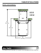
TABLETOP SOLUTIONS DIAGRAM 4: FRONT VIEW DIMENSIONS TABLE THICKNESS MIN. 3/4'' [19 mm] MAX.
TABLETOP SOLUTIONS DIAGRAM 5: SIDE VIEW DIMENSIONS SIDE VIEW 147 8'' [378 mm] 93 4'' [248 mm] 1'' 82 [216 mm] 400-0464-003 8
TABLETOP SOLUTIONS DIAGRAM 6: STANDARD PLATES US & UK DS901-130 DS901-131 Standard on PNP517 for United States. PNP517C with configurable snap-ins. DS901-122 DS901-125 Standard on PNP527 for United Kingdom. PNP527C with configurable snap-ins.
TABLETOP SOLUTIONS DIAGRAM 7: STANDARD PLATES AU & GR DS901-123 DS901-122 Standard on PNP537 for Australia. PNP537C with configurable snap-ins. DS901-124 DS901-127 Standard on PNP547 for Germany. PNP547C with configurable snap-ins.
TABLETOP SOLUTIONS INSTALLING YOUR PNP515 7.2 POWER/SIGNAL CONNECTIONS 6 Connect external devices to the appropriate connector on the PNP. Remember, the devices plugged into the AC power connectors should not draw more than 5A AC. Step 1. Refer to the ALTINEX website, www.altinex.com, to download the latest templates and instructions for tabletop cutting requirements and installation instructions. TROUBLESHOOTING GUIDE In order to do this, locate the PNP515 on the website and go to its detail page.