MATRIX SWITCHERS MANUAL PART NUMBER: 400-0026-004 PRODUCT REVISION: 2 HOMERUN SERIES MATRIX SWITCHERS USER’S GUIDE
MATRIX SWITCHERS INTRODUCTION TABLE OF CONTENTS Page Thank you for purchasing a HOMERUN Series Matrix Switcher. We are sure you will find it to be reliable and simple to use. PRECAUTIONS/SAFETY WARNINGS..................2 GENERAL ..........................................................2 INSTALLATION ..................................................2 RACK-MOUNT INSTALLATION .........................2 CLEANING .........................................................2 FCC NOTICE.........................
MATRIX SWITCHERS PRECAUTIONS/SAFETY WARNINGS 1-U rack space for every 4 HOMERUN Switcher modules for air circulation. This will reduce heat build up and will prolong the life of the HOMERUN Switcher. 1 Please read this manual carefully before using your HOMERUN Series Matrix Switcher. Keep this manual handy for future reference. These safety instructions are to ensure the long life of your HOMERUN Series Matrix Switcher and to prevent fire and shock hazard.
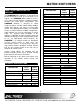
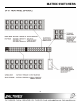
MATRIX SWITCHERS FEATURES/ DESCRIPTION ABOUT YOUR HOMERUN MATRIX SWITCHER 2 Switching Time Gain Power Internal Power Supply Power Input Video Audio The HOMERUN Matrix Switcher is a state-of-the-art product designed to route up to 16 inputs to 16 outputs. The HOMERUN Matrix Switcher consists of 1-U high rack wide modules. Combining multiple modules can create larger configurations.
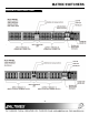
MATRIX SWITCHERS DIAGRAM OF FRONT/BACK PANEL 4 4
MATRIX SWITCHERS 5
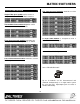
MATRIX SWITCHERS APPLICATION DIAGRAM 5 Five interconnected modules would be used for RGBHV Signals. Single Video/Sync module can be used as a Composite Video or TTL/ECL Matrix Switcher. Two modules interconnected together can be used as an S-Video Matrix Switcher. A single Audio Module is designed to route a Balanced Mono Audio signal. Three interconnected modules can route any analog component video signals such as RGsB. Two Audio modules interconnected can be used to route Stereo Audio Signals.
MATRIX SWITCHERS INSTALLING YOUR SWITCHER Step 1. 1 through 16, and the outputs to audio receivers. 6 Stack together the modules that are required to form a matrix for switching the desired signals. CAUTION: All video inputs to HOMERUN Video Modules are DC coupled for best performance. Even though the video inputs are fully isolated, verify with an electrician that all of the grounding is proper and that GROUND LOOP problems are minimized. Severe Ground loop type conditions can damage equipment.
MATRIX SWITCHERS seconds until you hear a beeping sound and release the button. This will disable the selected output. RESET SELECTED CHANNELS: Press the F1 & F2 switches simultaneously and release them quickly to reset the connection of the selected input & output. Figure 2: HOMERUN Video Module OPERATION RESET TO DEFAULT: To reset the unit to its default status (power-on stage) press and hold the F1 & F2 switches simultaneously for approximately three seconds until you hear a beeping sound.
MATRIX SWITCHERS 1.
MATRIX SWITCHERS This command sets a unique ID number to each HOMERUN module and allows control of multiple modules through a single RS-232 port. [CODEn] n In order to control multiple modules independently with one RS-232 port, the unit ID is used. Setting the unit ID allows a user to send the same command to multiple modules, but the module processes that command with the indicated ID number only. The factory default unit ID=1.
MATRIX SWITCHERS This command is used for programming the switcher. It should not be used as part of a program to operate the switcher. There is no feedback provided for this command. switcher; it should not be used as part of a program to operate the switcher. There is no feedback provided for this command. [IXXOmmA] mm = output offset; 00 to 96 [IkkOXXS] kk = input offset; 00 to 96 This command sets the offset number for outputs. It is used when multiple switchers are connected to form a larger matrix.
MATRIX SWITCHERS to outputs, as saved in memory position #1. There is no feedback provided, but the unit will beep after execution of this command. This command is the equivalent of turning ON the unit. 3. The input offset must be set for all units except the first one. The offset for input should be the same as the last input number of the previous unit. 4.
MATRIX SWITCHERS [ERR], just the version number; for example [3.2] or [3.5]. [VISn] n = 1 Enable VIS n = 0 Disable VIS This command enables or disables vertical interval switching, if the option is installed on the HOMERUN Matrix Switcher. UNIT ID - n 7.2.3 CONTROL COMMANDS These control commands are used for controlling the switcher. They can be part of a normal program to operate the switcher. These command actions are lost if power is disconnected from the unit, or if the unit is reset in any way.
MATRIX SWITCHERS command. The [UIDnE] command should be used to disable all levels and enable only the unit that needs to be controlled. This command can not be used with unit ID 0 or 1. example, in a RGBHV + Mono Audio combination where RGB = Unit ID2, HV = Unit ID3, and Mono Audio = Unit ID4, the [I12O10U2] command will connect input 12 to output 10 on RGB units and not on HV or audio modules. [I03O10U4] will connect input 3 to output 10 on audio modules and not on RGBHV units.
MATRIX SWITCHERS This command selects the output to control. Once the output number to be controlled is set through this command, this output can be connected to several inputs. If output 00 is selected then disconnect all inputs to be specified through the connect command, [IkkOXXC]. For example, to connect input 2 to 3, 8 to 10 & leave other outputs as the same as the command will be issued as follows, [CAXXXX02XXXXXXXX02XX02XXXXXXXXX XXX].
MATRIX SWITCHERS where mm is the current input connected to the specified output. CONTROL OPERATION Connect any input to any output: For example, the [IXXO02] command can return 04 indicating that input #4 is currently connected to output #2. [IXXO03] can return 00, which means that nothing is currently connected to output #3. Press the desired input, 1 through 16. The input LED will flash slowly. The LED on the outputs that are already connected to the selected input will flash quickly.
MATRIX SWITCHERS Press the RECALL button and hold for 2 seconds. The unit will beep and switch into the recall mode. This mode is indicated by the RECALL LED flashing slowly. Press INPUT 1 through INPUT 16 to recall the desired memory location. Output buttons do not work anymore in this operation. Set Unit ID numbers This function is used to control individual levels of the HOMERUN Matrix Switcher, such as switching video and audio separately.
MATRIX SWITCHERS Turn Power ON for all connected HOMERUN modules. Set Baud Rate: Baud rate determines communication between the control system and HOMERUN Matrix Switchers and also the rate between individual modules of the HOMERUN. Setting all interconnected modules to the same baud rate is essential for proper operation of the complete system. It is recommended that baud rate is changed for all modules when the HOMERUN Switcher’s modules are connected together.
MATRIX SWITCHERS end of the cable is connected to the RS-232 port of the HOMERUN Matrix Switcher. VW=7 ALTINEX HOMERUN CONTROL PROGRAM 1 Follow Step 1 of previous option. 2. Load the HOMERUN control program on WINDOW 95 from the START UP button, PROGRAM option and Altinex tab. 3 Go to the SETUP TAB and verify that current baud rate is set at 2400 baud (default). Then from SET Baud Rate section select 9600 baud and click the program button to program the baud rate into all attached HOMERUN modules.
MATRIX SWITCHERS to be saved in any of the 16 available memories. RECALL Allows recalling the saved connections from memory 01 through 16. SPACE Reserved for future use. DELETE Reserved for future use. CLEAR Reserved for future use. Recall 01,02,03 Allows the end user to recall the first three settings by pressing just one button. ENTER SAVE? 2. SAVE? 05 E. Recalling Your Settings: There are two ways to recall your settings: Quick Recall and Standard Recall.
MATRIX SWITCHERS ACCESSORIES Model No.
MATRIX SWITCHERS 8 9 at the same time, can this be done with this product? Can I use contact closure to control the switcher? Is the HOMERUN Switcher capable of controlling various projectors? TROUBLESHOOTING GUIDE a challenge to connect. No. The unit should be controlled using RS-232 commands or through the optional CP-01/CP-02/CP-03 It is not recommended in large size systems to control a projector through the switcher.
MATRIX SWITCHERS DOWNLOAD section from the Altinex website www.altinex.com. ALTINEX POLICY returned without an RMA experience a delay in service. number may If your product is out of warranty and needs service, contact the Altinex Sales Department for an RMA (Return Material Authorization). Products returned without an RMA number may experience a delay in service. The service charges will be quoted to you before actual repairs are done. 11 11.