INTERFACES MANUAL PART NUMBER: 400-0049-003 PRODUCT REVISION: 0 VA6831FC DUAL INPUT/SWITCHABLE ANALOG INTERFACE USER’S GUIDE
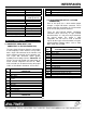
INTERFACES TABLE OF CONTENTS INTRODUCTION Page Thank you for purchasing the VA6831FC Dual Input/Switchable Analog Interface. We are sure you will find it reliable and simple to use. PRECAUTIONS / SAFETY WARNINGS ...............2 GENERAL ..........................................................2 Superior performance for the right price, backed by solid technical and customer support is what Altinex has to offer. RACK MOUNT SAFETY GUIDELINES. ............2 INSTALLATION..................................
INTERFACES PRECAUTIONS / SAFETY WARNINGS 1 Please read this manual carefully before using your VA6831FC Interface. Keep this manual handy for future reference. These safety instructions are to ensure the long life of your VA6831FC and to prevent fire and shock hazard. Please read them carefully and heed all warnings. • • 1.1 GENERAL • • • Unauthorized personnel shall not open the unit since there are high-voltage components inside.
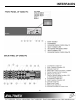
INTERFACES ABOUT YOUR INTERFACE 2 Stereo Audio Output Connector Compatibility There are several varieties of computers and computer video cards on the market today. There are also numerous data monitors and large screen data projectors. When displaying a computer image on a large screen data projector or on a large screen monitor, it often becomes clear that some computers are not always compatible with these display devices.
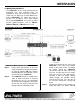
INTERFACES Cross-talk Signal-to-Noise Ratio Bandwidth Stereo Channel Separation Frequency Compatibility Horizontal Vertical Minimum Video Bandwidth Horizontal Position Range Cross-talk Power Internal Power Supply Power Consumption Table 3. VA6831FC Electrical Ohms) <80dB @ 1 kHz >95dB 10 Hz – 40 kHz >75dB @ 1 kHz, >60dB @ 20 kHz 12 13 14 15 Table 4. VA6831FC Dual Input pin-outs 4.
INTERFACES 5
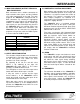
INTERFACES 4.5 HORIZONTAL POSITION ADJUSTMENT 4.3 MAIN (RGBS/RGBHV) OUTPUT THROUGH 6 BNC CONNECTORS Most monitors and projectors have the ability to adjust the horizontal position of the image, but sometimes it is helpful to control this feature at the interface. This control is especially useful when multiple computers are switched to a single display if the Horizontal positions for each computer is slightly different.
INTERFACES 4.8 MOUNTING CAPABILITY The VA6831FC can be easily mounted into an equipment rack. Four mounting holes are provided on each side of the unit. To mount a single unit, use Altinex 19”-1U Rack Mount Ears (part # DA1294FC). To mount two units in tandem, use an Altinex 19”-1U Rack Mount Shelf (part # DA1293FC). For under the table mounts, optional brackets, such as TM1271, TM1272, TM1273, or TM1274 can be used. APPLICATION DIAGRAM 5 INSTALLING YOUR INTERFACE 6 Step 1.
INTERFACES light on the front panel of the VA6831FC should turn on. Step 4. Connect one end of the input cable to the video output of the computer and the other end to the 15-pin HD input connector of the VA6831FC. Repeat this step if two computers are to be interfaced. Step 5. Connect a cable from a local monitor to the 15-pin HD Local Monitor Output connector of the interface. Repeat this step for a second local monitor if two computers are to be interfaced.
INTERFACES position of the image can be adjusted through the Horizontal Position Control knob located on the front panel. Similarly, one can only adjust the position of the image on the display for Input 2 using the Horizontal position control knob when the CH2 Horizontal Delay switch is in the OFF position. Model No.
INTERFACES FAQ (FREQUENTLY ASKED QUESTIONS) 9 No: 1. 2. 3. 4.
INTERFACES ALTINEX POLICY If your product is out of warranty and needs service, contact the Altinex Sales Department for an RMA (Return Material Authorization). Products returned without an RMA number may experience a delay in service. The service charges will be quoted to you before actual repairs are done. 11 11.1 LIMITED WARRANTY Altinex warrants that its products and cables are free from defects in materials under normal use and service.