
Operation Manual


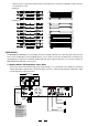


6. Breaker
This breaker is used to protect the unit in replacement of fuse. Press it to reset.
7. AC Inlet
This connector is meant for the connection of the supplied main cord. Do not insert the power cord into this
unit until voltage has been correctly set. Do not plug the power cord into the mains until the voltage has been
correctly set.
8. Output Connectors
The Output Connectors include the Speak-on jacks and Binding post terminals, you can use the specific Output
connectors according to the actual application circumstance.
Be careful to connect the Output Connectors so as not to occur any problem.
Caution: Turn off the unit before connecting the Output Connectors so as to avoid any electric shock!
9. Balanced Input Connectors
The Input Connectors include the balanced XLR servo connectors and 1/4" TRS phone jack. For the extension
to another amplifier, connect these jacks to another amplifier input jacks.
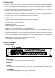
4. Level controls for CHANNEL A, B
These level Controls are used to adjust the output signal level, you'd better adjust them properly to avoid any distortion.
5. Protection LED
This red LED indicator lights up when the thermal-protection system is working, no signal is output during this protec-
tion period, and this means any overheating occurs inside the unit (the critical temperature is 80℃), you must take
actions to avoid this overheating, e.g.: speed up the air circulation, decrease the signal level. If the problem is corrected,
the protection systems deactivate automatically, this LED eliminates, and normal amplifier operation is resumed .
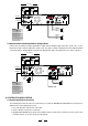
3.2 The Rear Panel
While on, the clip limit function specific to this machine keeps fixed output when the output exceeds the Max-
imum of the machine to protect its circuits. While off, there is no such limit.
10. Clip Limit Switch
The MACRO 830/1400/2400 Professional Stereo Amplifier presents three operating modes:
In this mode, Channel A and Channel B operate independently (as a conventional stereo amplifier).
The Channel A input signal will be output from the Channel A output connectors, and the Channel B input signal
will be output from the Channel B output connectors.
- Parallel Mono Mode
In this mode, the Channel A input signal will be output from the output connectors of both Channels, detail wiring diagram
you can refer to Chapter 5.
In this mode, the Channel A input signal will be output from the Bridge output connectors, detail wiring diagram you
can refer to Chapter 5.
11. Mode Selector
- Bridged Mode
- Stereo Mode
Some large subsonic frequencies are present in the input signal and these can damage the consequent
12. LF 30Hz Filter
11
89 10 13
6
12 7
INPUT
CONNECTION
12
3
(+)
(GND)
BR E AKER
BRIDGED
MONO
CH A NNEL A CH A NNEL B
CH-B
CH-A
BRIDGED INPUT
LINE
BALANCED
INPUT
OFF
LF 30HZ
FILTER
LINE
ON
OFF ON
CLIP LIMIT
BRIDGED
STEREO
PARALLEL
(MONO)
1.15V/20KΩ
( )
SRT
T(+)
R( )
S(GND)
SERIAL
MODEL
WARNING
TO REDUCE THE RISK OF FIR E
OR ELECTRIC SHOC K, DO NOT
EXPOSE THIS APPARATU S TO
RAIN OR MOISTURE .
SEE INSTRUCTIO N BEFORE
USING!
2
1
3
2
1
3
5