R LTO User's Manual MISTRAL 400 STEREO POWER AMPLIFIER www.altoproaudio.com Version 1.0 NOV.
IMPORTANT SAFETY INSTRUCTION CAUTION RISK OF ELECTRIC SHOCK DO NOT OPEN TO REDUCE THE RISK OF ELECTRIC SHOCK PLEASE DO NOT REMOVE THE COVER OR THE BACK PANEL OF THIS EQUIPMENT. THERE ARE NO PARTS NEEDED BY USER INSIDE THE EQUIPMENT. FOR SERVICE, PLEASE CONTACT QUALIFIED SERVICE CENTERS. WARNING To reduce the risk of electric shock and fire, do not expose this equipment to moisture or rain. Dispose of this product should not be placed in municipal waste and should be separate collection. 11.
IN THIS MANUAL: 1. 2. 3. 4. 5. 6. INTRODUCTION.........................................................................1 FEATURES................................................................................1 CONTROL ELEMENTS................................................................2 APPLICATION............................................................................4 TECHNICAL SPECIFICATIONS.......................................................7 WARRANTY........................................
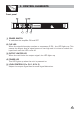
SP OT L 3. CONTROL ELEMENTS IG HT Front panel 1 2 3 R LTO 5 4 5 1 POWER SWITCH It switches the amplifier ON and OFF. 2 CLIP LED When the signal distortion reaches or surpasses 0.5% , the LED lights up. This means the output level of signal source is too high and it is time to reduce the input level until the LED turns off. 3 OUTPUT LIMITER LED When the unit limits the output signal, the LED lights up. 4 POWER LED This LED lights up when the unit is powered on.
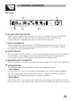
SP OT L 3. CONTROL ELEMENTS IG HT Rear panel 8 CH2 MODE STEREO BRIDGE NEW TIDE CH1 INPUT TIP/PIN 2 RING/PIN 3 SLEEVE/PIN 1 LIMITER 3 2 6 OFF ON 1 NEW TIDE TIP/PIN 2 RING/PIN 3 SLEEVE/PIN 1 CH2 1+ 1POS NEG CH2 SP SP POWER OUTPUTS 2 CH1 SP SP TIP 3 1 Class two wiring TIP CH1 1+ 1POS NEG CH2 2+ 2POS NEG BRIDGE 1+ 2+ POS NEG Apparaten skall anslutas till jordat uttag nar den ansluts till ett natverk AC INPUT: 110-120V 50-60Hz FUSE: T3.
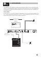
4. APPLICATION The MISTRAL 400 amplifier provides two operating modes: stereo mode and bridge mode, you can decide each specific operating mode according to your actual application circumstance. Please see following diagram for connecting the power amplifier into your audio system. - Stereo Mode In this mode, CH 1 and CH 2 operate independently (as a normal stereo amplifier).
4. APPLICATION - Stereo Mode Input Connector Balanced GND 1 3 2 INPUT CH2 MODE STEREO BRIDGE NEW TIDE CH1 INPUT TIP/PIN 2 RING/PIN 3 SLEEVE/PIN 1 LIMITER 3 2 OFF ON 1 NEW TIDE TIP/PIN 2 RING/PIN 3 SLEEVE/PIN 1 CH2 1+ 1POS NEG CH2 SP SP POWER OUTPUTS CH1 SP SP TIP 3 2 1 Class two wiring TIP CH1 1+ 1POS NEG CH2 2+ 2POS NEG BRIDGE 1+ 2+ POS NEG Apparaten skall anslutas till jordat uttag nar den ansluts till ett natverk AC INPUT: 110-120V 50-60Hz FUSE: T3.
4. APPLICATION - Bridge Mode In this mode, the CH 1 input signal will be output from the bridge output connector. On the other hand, the output level control of CH 2 should be turned down to minimum (turn the volume control at counterclockwise). Only the volume control of CH 1 is used to control the volume of the whole system.
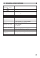
5. TECHNICAL SPECIFICATIONS TYPE MISTRAL 400 Stereo Mode - (4 ohms) (EIAJ) 100W x 2 Stereo Mode - (4 ohms) (RMS) 70 W x 2 Distortion (SMPTE-IM) <0.05% Frequency Response 20 Hz-20 kHz 0.
6. WARRANTY 1. WARRANTY REGISTRATION CARD To obtain Warranty Service, the buyer should first fill out and return the enclosed Warranty Registration Card within 10 days of the Purchase Date. All the information presented in this Warranty Registration Card gives the manufacturer a better understanding of the sales status, so as to provide a more effective and efficient after-sales warranty service.
SEIKAKU TECHNICAL GROUP LIMITED NO. 1, Lane 17, Sec. 2, Han Shi West Road, Taichung 40151, Taiwan http://www.altoproaudio.com Tel: 886-4-22313737 email: alto@altoproaudio.com Fax: 886-4-22346757 All rights reserved to ALTO. All features and content might be changed without prior notice. Any photocopy, translation, or reproduction of part of this manual without written permission is forbidden.