
Operation Manual


3. CONTROL ELEMENTS
SPOTLIGHT
6
7
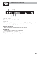
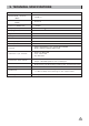
LIMITER SWITCH
Set the switch at "ON" position, if a very high level signal is driven into the amplifier,
the clip begins, thus keeping consistent output level for protecting apparatus.
If the switch is set at "OFF" position, this clip function doesn't work.
8
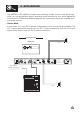
OUTPUT CONNECTOR
These connectors have two kinds: 1/4 TRS jack and Neutrik connector. You can
choose proper connectors according to practical need. For your safety, please
be careful when do connecting work.
9
10
BALANCED INPUT CONNECTOR
These connectors are used to connect the input signal of CH 1 and CH 2 separately.
3
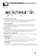
AC INLET AND FUSE HOLDER
Connect the supplied main cord. Do not insert the power cord into the MISTRAL
400 amplifier and into the AC Outlet until voltage has been correctly set.
If the fuse blows, replaced with a fuse of the correct type only.
Rear panel
MODE SELECTOR
The MISTRAL 400 power amplifier presents two operating modes:
- Stereo Mode
In this mode, CH 1 and CH 2 operate independently (as a normal stereo amplifier).
The CH 1 input signal will be output from the CH 1 output connector, and CH 2
input signal will be output from the CH 2 output connector.
- Bridge Mode
In this mode, CH 1 input signal will be output from the bridge-mono output connector.
On the other hand, the output level control of CH 2 should be turned to the minimum.
10
9
8
7
6
CH2
INPUT
CH1
POWER
OUTPUTS
LIMITER
OFF
ON
TIP
SP
SP
TIP
SP
SP
MODE
BRIDGE
STEREO
TIP/PIN 2
RING/PIN 3
SLEEVE/PIN 1
TIP/PIN 2
RING/PIN 3
SLEEVE/PIN 1
CH1
1+ 1-
POS NEG
CH2
2+ 2-
POS NEG
BRIDGE
1+ 2+
POS NEG
CH2
1+ 1-
POS NEG
21
3
NEW TIDE
21
3
NEW TIDE
CH2 CH1
AC INPUT:110-120V 50-60Hz
FUSE: T3.15AL 250VAC
Rated Power Consumption 200W
REPLACE FUSE WITH CORRECT TYPE ONLY
Apparaten skall anslutas
ansluts till ett natverk
till jordat uttag nar den
Class
two wiring
Class
two
wiring