
Operation Manual


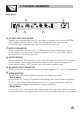


- Bridge Mode
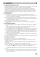
4. APPLICATION
In this mode, the CH 1 input signal will be output from the bridge output connector.
On the other hand, the output level control of CH 2 should be turned down to minimum
(turn the volume control at counterclockwise). Only the volume control of CH 1 is used
to control the volume of the whole system.
6
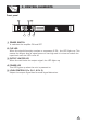
Input Connector
Balanced
1
2
3
GND
INPUT
+
CH 1
CH 1
Bridge Mode
Press this button
CH 2
CH2
INPUT
CH1
POWER
OUTPUTS
LIMITER
OFF
ON
TIP
SP
SP
TIP
SP
SP
MODE
BRIDGE
STEREO
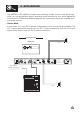
TIP/PIN 2
RING/PIN 3
SLEEVE/PIN 1
TIP/PIN 2
RING/PIN 3
SLEEVE/PIN 1
CH1
1+ 1-
POS NEG
CH2
2+ 2-
POS NEG
BRIDGE
1+ 2+
POS NEG
CH2
1+ 1-
POS NEG
21
3
NEW TIDE
21
3
NEW TIDE
CH2 CH1
AC INPUT:110-120V 50-60Hz
FUSE: T3.15AL 250VAC
Rated Power Consumption 200W
REPLACE FUSE WITH CORRECT TYPE ONLY
Apparaten skall anslutas
ansluts till ett natverk
till jordat uttag nar den
Class
two wiring
Class
two
wiring