
Service manual


#8311 O&C MANUAL• TH/III FAMILY
PG. 19
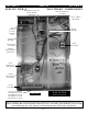
SECTION 5 SERVICE SECTION 5
Do not replace any electrical components without first disconnecting electrical power
to the unit by the ON/OFF switch at the back of the oven. A sign indicating the oven is
being serviced and that the power must remain OFF should be posted on the panel.
500-TH/III
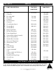
PART DESCRIPTION 750-TH/III 1200-TH/III
1000-TH/III
1. Fan Cord CD-33338 CD-33338
Connector CR-3596
2. Fan, 208/240V FA-3568 FA-3568
Fan, 120V FA-3599 FA-3574
Connector CR-33509
3. Fan Thermostat TT-33255 TT-33255
Connector CR-3849
4. Circuit Breaker Switch SW-33858 SW-3715
5. Terminal Block BK-3019 BK-3019
Terminal Block BK-3023
6. Beeper, Solid State BP-3567 BP-3567
7. Hi-Limit Thermostat TT-33476 TT-33476
8. Power Supply Board BA-33554 BA-33554
9. Voltage Monitor Board Assembly BA-33764 BA-33764
10. Sensor Terminal Block BK-33546 BK-33546
11. Modular Block Assembly BK-33364 BK-33364
12. Sensor, Air Temperature SN-33540 SN-33540
13. Switch Reed for Door SW-33559 SW-33559
14. Relay RL-33829 RL-33829
Heat Sink Pad HE-33926 HE-33926
15. Cordset, 120V CD-33824
Cordset, 208-240V CD-3588
Cord CD-3304
Cordset, 230V,
500-TH/III only CD-3922
Cordset, 230V CD-33882
Plug (UK and Hong Kong) PG-33368
16. Ground Screw SC-2190 SC-2190
17. Control CC-34063 CC-34063
ELECTRONIC COMPONENTS