® COMBITHERM ® INSTALLATION MAINTENANCE SERVICE ELECTRIC ML SERIES COMBINATION OVEN/STEAMERS W164 N9221 Water Street PHONE: (262)251-3800 ● P.O. Box 450 (800)558-8744 U.S.A./CANADA ● Menomonee Falls, Wisconsin 53052-0450 FAX: (262)251-7067 ● U.S.A. (800)329-8744 U.S.A. (262)251-1907 INTERNATIONAL www.alto-shaam.
COMBITHERM ® TABLE OF CONTENTS ELECTRIC INSTALLATION SERVICE SECTION Receiving & Transportation . . . . . . . . . .1 Basic Installation Site Requirements . . . . . .2 Ventilation Requirements . . . . . . . . . . .2 Positioning On Site . . . . . . . . . . . . . . . .3 Installation Requirementss . . . . . . . . . .4 Hand Shower Assembly . . . . . . . . . . . . .5 Wat e r S u p p l y . . . . . . . . . . . . . . . . . . . .5 Wa t e r D r a i n a g e . . . . . . . . . . . . . . . . . . .
C O M B I T H E R M ® I N S TA L L AT I O N RECEIVING & TRANSPORTATION Upon receipt of the Combitherm combination oven/steamer, check the exterior of the shipping carton for any physical damage that could result in damage to the contents. If the oven was not received from the carrier in an upright position, there is a stronger possibility of concealed damage. Remove the carton or uncrate the unit carefully and inspect for any transit damage. Immediately report any damage to the delivering freight carrier.
C O M B I T H E R M ® I N S TA L L AT I O N BASIC INSTALLATION SITE REQUIREMENTS H O O D I N S TA L L AT I O N I S R E Q U I R E D • Installation surface must be level. • Do not install adjacent to flammable surfaces. • Deep fat fryers or similar heat producing equipment must not be installed in the immediate vicinity of the hand shower. The oven must remain on the pallet while being moved to the installation site with fork lift or pallet lift truck. Do not tilt the oven.
C O M B I T H E R M ® I N S TA L L AT I O N POSITIONING ON SITE removing the oven from the pallet for ➤Before positioning on site, it is important to remove the drip tray to prevent damage to the tray caused by the lifting forks. The drip tray is fastened to the bottom of the oven with three sheet metal screws as illustrated. This requirement pertains to the following models. MODELS 6•10 ML 10•10 ML 7•14 ML 10•18 ML This step does not pertain to models 12•20 ML and 20•20 ML .
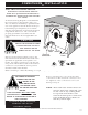
INSTALLATION REQUIREMENTS ■ Do not install oven adjacent to flammable 4" (102mm) surfaces. Strictly observe all local fire safety regulations. ■ In order to ensure proper ventilation, a minimum distance of at least 6-inches 18" (46cm) (152mm) must be kept from the control panel side [ LEFT ] of the oven and any adjoining surfaces. 4" (102mm) NOTE: In addition to ventilation RETRACTABLE DOOR OPTION: requirements, additional clearance 6-1/2" (165mm) is needed for service access.
C O M B I T H E R M ® I N S TA L L AT I O N ASSEMBLY REQUIREMENTS HAND SHOWER HOLDER Fasten the hand shower holder in the holes provided on the oven using the three (3) screws packaged with the holder. WATER SUPPLY C O N N E C T TO P OTA B L E ( D R I N K A B L E ) C O L D WAT E R O N LY WATER PRESSURE REQUIREMENTS: M I N I M U M 30 PSI (2 BAR) MAXIMUM 90 PSI (6 BAR) Flush the water line at the installation site before connecting the oven to the water supply.
C O M B I T H E R M ® I N S TA L L AT I O N WATER DRAINAGE The oven must discharge through an indirect waste pipe by means of an air gap. The drain thread is 1-1/4-inch (32mm) NPT. A union is required. Install a 1-1/4-inch (32mm) diameter drain line. The drain line must always be a positive gradient away from the Combitherm oven and not more than 12-inches (305mm) before an air gap. NOTE: In the U.S.A.
C O M B I T H E R M ® I N S TA L L AT I O N ELECTRICAL INSTALLATION ELECTRICAL CONNECTIONS MUST BE MADE BY A QUALIFIED ELECTRICIAN IN ACCORDANCE WITH APPLICABLE ELECTRICAL CODES. An electrical wiring diagram is located behind the control panel on the left side of the oven. The oven must be installed by a qualified electrician. This appliance must be branch circuit protected with proper ampacities, in accordance with the wiring diagram located in the electrical compartment of the oven.
A D D I T I O N A L T E C H N I C A L D ATA MODEL ➜ Type of Oven Pan INCHES Capacity GASTRONORM 6•10 M L 10•10 M L 7•14 M L 10•18 M L 12•20 M L 20•20 M L counter counter counter counter floor floor oven stand oven stand oven stand oven stand w/roll-in cart w/roll-in cart 6: 12" x 20" 10: 12" x 20" 14: 12" x 20" 20: 12" x 20" 24: 12" x 20" 40: 12" x 20" 6: 18" x 13" 10: 18" x 13" 7: 18" x 26" 10: 18" x 26" 12: 18" x 26" 20: 18" x 26" 6: GN 1/1 10: GN 1/1 14: GN 1/1 20: GN
C O M B I T H E R M ® I N S TA L L AT I O N INSTRUCTIONS TO BE PROVIDED TO OWNER/OPERATOR ■ INITIALS / DATE Owner/operator has been instructed on proper method of flushing the steam generator and safe procedures for handling the steam generator drain cap. ■ Owner/operator has been instructed on the importance of cleaning the oven along with proper cleaning procedures including automatic steam generator flush, daily cleaning of the interior, and monthly decalcification.
ELECTRIC COMBITHERM INSTALLATION CHECKLIST ® Use this list as a final check of oven installation conformance. Damage directly attributed to improper set up, installation, or cleaning can invalidate warranty claims. CLEARANCES: All clearances must conform with the standards set by Alto-Shaam as indicated in the installation manual. Standards include a minimum 20” (50cm) clearance from any heat-producing device such as an open burner range, flat top grille, fryer, steamer, etc.
I M P O R TA N T S A F E T Y P R E C A U T I O N S For safe release of the cooking compartment steam, initially open the door approximately 2" (50mm) only. Stand behind the door as the hot STEAM steam is released. DO NOT USE THE ATTACHED HAND-HELD HOSE TO SPRAY ANYTHING OTHER THAN THE INTERIOR OF THE COMBITHERM OVEN COMPARTMENT. AT NO TIME SHOULD THE EXTERIOR OF THE OVEN BE STEAM CLEANED, HOSED-DOWN WITH THE HAND-SPRAYER, FLOODED WITH WATER, OR FLOODED WITH LIQUID SOLUTION OF ANY KIND.
C O N T R O L PA N E L I D E N T I F I C AT I O N POWER ON/OFF KEY STEAM MODE KEY RETHERM MODE KEY START / STOP KEY SUPERHEATED STEAM AND CONVECTION MODE KEY CONVECTION MODE KEY PROGRAMMED MENU KEY PROGRAM INSTALL/EDIT KEY DELUXE MODELS ONLY DELUXE MODELS ONLY CHEF FUNCTION KEY FUNCTION & OPERATING INDICATORS COOKING TEMPERATURE KEY CONTROL PANEL DISPLAY CORE TEMPERATURE KEY UP ARROW KEY QUICK PROGRAM KEYS TIME KEY DOWN ARROW KEY ADJUSTMENT KNOB DELUXE MODE
C O N T R O L PA N E L I D E N T I F I C AT I O N POWER ON/OFF KEY Activates power to the oven and automatically fills the steam generator with water which will heat to a stand-by mode temperature of 150°F (65°C). The steam generator flush is also activated by pressing this key. START/STOP KEY Initiates all cooking mode functions and programmed procedures stored in memory. Stops an activated cooking mode or programmed procedure currently in progress, and exits Chef function key.
S - C O N T R O L PA N E L I D E N T I F I C AT I O N OFF POSITION Maintains oven in a stand-by mode. STEAM The oven will operate at a fixed steam temperature of 212° F (100°C). COMBINATION A combination of steam and convection heat to cook at a temperature between 86°F and 482°F (30°C to 250°C) to be set by the operator. CONVECTION Convection heat to cook without steam at a temperature between 86°F and 482°F (30°C and 250°C) to be set by the operator.
COMBITHERM® CLEANING & MAINTENANCE Preventive Maintenance In addition to the routine cleaning and maintenance procedures, there are several additional steps to be taken for both sanitation purposes and to keep the oven running at top operating efficiency. These additional safeguards will help prevent inconvenient down time and costly repairs. ● DO NOT DISPOSE OF GREASE, FAT, OR SOLID WASTE DOWN THE OVEN DRAIN. Fats and solids will eventually coagulate in the drain system, causing blockage.
AU TO M AT I C S T E A M G E N E R ATO R F L U S H STANDARD CONTROL DELUXE CONTROL AT T H E S TA RT O F E AC H WO R K DAY STANDARD CONTROL DELUXE CONTROL Flushing the electric Combitherm steam generator on a daily basis helps to prolong the life of the steam generator heating elements and helps prevent the necessity of service requirements. The control provides this feature as an automatic function when the oven ON/OFF power key is pressed to the ON position at the start of each working day.
COMBITHERM® CLEANING & MAINTENANCE RUBBER GLOVES AND PROTECTIVE EYE WEAR MUST BE WORN WHEN USING THE OVEN CLEANER. USE AUTHORIZED COMBITHERM L I Q U I D O V E N C L E A N E R O N LY Unauthorized cleaning agents may discolor or harm interior surfaces of the oven. Read and understand label and material safety data sheet before using the oven cleaner. Causes severe burns. Do not get in eyes, on skin, or on clothing. Do not wear contacts. Harmful or fatal if swallowed. Do not breathe mist.
CONTROL OPTION COMBITHERM® CLEANING & MAINTENANCE CONTROL D A I LY O V E N C L E A N I N G OPTION The Combitherm automatic cleaning function selects the proper temperature for each step of the cleaning process. 1. Remove all food scraps and residue from the oven drain. Close the oven door securely. Rotate the power knob to the cleaning symbol. THE OVEN WILL BEGIN THE FIRST STEP IN A TWO-STEP CLEANING CYCLE • 10 MINUTES at full steam temperature of 212°F (100°C) 2.
STANDARD CONTROL DELUXE CONTROL COMBITHERM® CLEANING & MAINTENANCE D A I LY O V E N C L E A N I N G STANDARD CONTROL DELUXE CONTROL D O N O T S P R AY C L E A N E R INTO A HOT OVEN. ALLOW THE OVEN TO COOL TO 150°F (60°C). The temperature in the display indicates the air temperature inside the oven compartment and not the interior walls of the oven. Always make certain to allow the oven walls to cool to a minimum of 150°F (60°C) before spraying the compartment with oven cleaner. 1.
COMBITHERM® CLEANING & MAINTENANCE STANDARD CONTROL DELUXE CONTROL A U T O M AT I C C L E A N I N G P R O G R A M The Combitherm automatic cleaning function selects the proper temperature for each step of the cleaning process. With the oven power on: PRESS THE CHEF FUNCTION KEY. ➡ Rotate the adjustment knob until the clean symbol is highlighted in the display. PRESS THE CHEF FUNCTION KEY.
CONTROL OPTION C O M B I T H E R M ® D E C A L C I F I C AT I O N CONTROL OPTION It is VERY important to decalcify the oven, particularly in areas with extremely hard water. PERFORM ONCE A MONTH in addition to the daily steam generator flush. WITH THE OVEN AT ROOM TEMPERATURE 1. Begin decalcification with the power switch in the OFF position. 2. Rotate the Steam Generator Drain Cap until water begins to flow from the four holes in the cap.
C O M B I T H E R M ® D E C A L C I F I C AT I O N CONTROL OPTION TURN THE SELECTION KNOB TO THE STEAM POSITION. THE WATER IN THE STEAM GENERATOR WILL BEGIN TO HEAT. ALLOW THE OVEN TO REMAIN IN THIS POSITION FOR A MINIMUM PERIOD OF 10 MINUTES TO DECALCIFY THE STEAM GENERATOR. DO NOT TURN THE TIMER ON. Severe burns could occur.
STANDARD CONTROL DELUXE CONTROL C O M B I T H E R M ® D E C A L C I F I C AT I O N It is VERY important to decalcify the oven, particularly in areas with extremely hard water. STANDARD CONTROL DELUXE CONTROL PERFORM ONCE A MONTH in addition to the daily steam generator flush. WITH THE OVEN AT ROOM TEMPERATURE 1. Begin decalcification with the power switch in the OFF position. 2. Rotate the Steam Generator Drain Cap until water begins to flow from the four holes in the cap.
C O M B I T H E R M ® D E C A L C I F I C AT I O N STANDARD CONTROL DELUXE CONTROL PRESS THE ON/OFF POWER KEY TO THE ON POSITION. THE WATER IN THE STEAM GENERATOR WILL BEGIN TO HEAT. ALLOW THE OVEN TO REMAIN IN THIS POSITION FOR A MINIMUM PERIOD OF 10 MINUTES TO DECALCIFY THE STEAM GENERATOR. In the case of extreme calcification build-up such as in areas with very hard water, ovens can be left in this condition overnight. Follow the remaining instructions at the start of the next production day.
COMBITHERM® CLEANING & MAINTENANCE R O L L - I N C A RT / F O O D T R O L L E Y C L E A N I N G ( O N EQUIPPED MODELS ) 1. Remove food trolley to a cart wash area. Trolleys may be cleaned using any mild cleaning detergent and warm water. 2. Hand wipe all framing, slides, drip pan, and base. Thoroughly clean debris from the casters. A spray hose can be used for easier cart cleaning. 3. Remove detergent solution with warm water. 4.
E M E R G E N C Y O P E R AT I O N In the event of an error code, operation of the Combitherm can be continued on a limited basis for a short duration. Cooking times may be longer than normal operation and close monitoring of the cooking process is recommended. Contact an authorized service agency immediately if the problem cannot be rectified with simple steps in the troubleshooting guidelines located in this manual.
C O N T RO L R E S E T There is a remote possibility in the day-to-day operation of the Combitherm that the control could lock or freeze. If this occurs, the control is easy to reset. PRESS AND HOLD the Power Key for a period of 5 seconds. Release the Power Key. The control will reset itself within approximately 15 seconds. WHEN RESET, THE DISPLAY WILL INDICATE THE TIME AND DATE AND THE CONTROLS WILL BE FULLY FUNCTIONAL .
T RO U B L E S H O OT I N G ERROR CODE E23 DESCRIPTION OF ERROR Steam generator probe (B4 thermocouple) is interrupted. POSSIBLE CAUSE/REMEDY Probe connection is bad at X6 on the control module. Steam generator probe (B4) is defective. Bad probe connection. E25 Condenser probe (B3 thermocouple) is interrupted. Probe connection is bad at X6 on the control module. Condenser probe (B3) is interrupted or defective. Bad probe connection. E26 Safety temperature probe (N8 thermocouple) is interrupted.
SERVICE VIEW • OVEN INTERIOR REPRESENTING MODELS: 6•10, 7•14, 10•10, 10•18, 12•20 Directional Panel Door Latch Dowel LT-25836 Door Latch LT-25058 Steam Port Convection Element EL-3854 - 6•10 EL-3761 - 7•14, 10•10 EL-3979 - 10•18 EL-3853 - 12•20, 20•20 #6001 Fan Wheel WH-3708 - 6•10, 7•14.
SERVICE VIEW • SIDE PANEL ACCESS PICTURED: 7•14 ML 208/240V 3Ph GENERALLY REPRESENTING MODELS: 6•10, 10•10, 10•18, 12•20 Fan Intake FA-3568 Wiring Diagram Contactor, 50 Amp Contactor, 20 Amp CN-3731 CN-3652 Motor Protection Switch 3 PH only, SW-33378 CONVECTION ELEMENTS Immersion Element TOP: EL-33411 Immersion Element BOTTOM EL-33412 Valve Solenoid Triple, VA-25481 Contactor, 25 Amp CN-3654 Fuseholder, FU-3842 Fuse, SC15, FU-3775 Terminal, 4mm TM-3781 #6001 PG.
SERVICE VIEW Model 20•20ML SHOWN WITH OPTIONAL ROLL-IN PLATE CART PE-25319 PANEL OVERLAY (STANDARD CONTROL) KN-33735 Knob, Adjustment Rocker LT-25836 Door Latch Dowel LT-25058 Door Latch PR-33746 Product Probe GS-2954 Door Gasket GS-22576 Gasket, Trolley #6001 C O M B I T H E R M E L E C T R I C I N S TA L L AT I O N A N D M A I N T E N A N C E M A N UA L PG.
SERVICE VIEW • OVEN INTERIOR Model 20•20ML EL-3853 Convection Element 208-240V, 3 Ph 440-480V, 3 Ph NU-22759 Nut, Steam Port NOT SHOWN TT-3750 Safety Thermostat PI-23929 Pin, Pivot TWO REQUIRED BK-22100 Trolley Guide Block PR-33784 Oven Temperature Probe #6001 PG.
SERVICE VIEW • SIDE PANEL ACCESS Model 20•20ML FA-3568 Cooling Fan MOTOR ASSEMBLY, 2-SPEED 440V, 3 Ph: 5000602 208-240V, 3 Ph: 5000276 5000538 Steam Generator Assy 208/240/440V EL-33411 Element, Immersion EL-33412 Element, Immersion VA-25481 Water Solenoid Valve 3-Way NOT SHOWN HO-22255 HOSE, 1/2” (12,7mm) ID, Water #6001 C O M B I T H E R M E L E C T R I C I N S TA L L AT I O N A N D M A I N T E N A N C E M A N UA L PG.
SERVICE VIEW • SIDE PANEL ACCESS Model 20•20ML EL-3853 Convection Element CN-3731 Contactor, 50A CN-3652 SW-33378 Contactor, Switch, 20A Motor Protection FU-3775 Fuse, 15A FU-3842 Fuse Holder, 15A 3 Pole TOP MOTOR AND WIRING TREE A S S E M B LY FU-33040 Fuse, 45A FU-33039 Fuseholder, 60A, 3 Pole TM-3780 Terminal, 35mm FU-33814 Fuse, 2 Amp (2) FU-33451 Fuse, 6.3 Amp FU-33756 Fuse Holder TM-3778 Terminal, 4mm BOTTOM MOTOR AND WIRING TREE A S S E M B LY CN-3654 Contactor, 25A #6001 PG.
Parts List • Combitherm ML Electric 6• 10 7•14 10 •10 10•18 12•20 2 0•2 0 CT-22887 CT-22887 CT-22887 CT-22887 CT-22887 CT-22887 CT-22885 CT-22885 CT-22885 CT-22885 CT-22885 CT-22885 CT-22886 CT-22886 CT-22886 CT-22886 CT-22886 CT-22886 DOOR, CLIP LT-25080 LT-25080 LT-25080 LT-25080 — — DOOR DRAIN, OUTER DA-25073 DA-25073 DA-25073 DA-25073 N/A N/A DOOR, HANDLE INSERT HD-23084 HD-23084 HD-23084 HD-23084 HD-23084 HD-23084 DOOR HANDLE, RIGHT HAND HD-2934 HD-2934
Parts List • Combitherm ML Electric 6• 10 7•14 10 •10 10•18 12•20 2 0•2 0 BOARD, DISPLAY CONTROL BA-33732 BA-33732 BA-33732 BA-33732 BA-33732 BA-33732 — ADJUSTING ROCKER ( COMPLETE ) KN-33734 KN-33734 KN-33734 KN-33734 KN-33734 KN-33734 — ADJUSTING ROCKER KNOB KN-33735 KN-33735 KN-33735 KN-33735 KN-33735 KN-33735 — BUSHING, DISTANCE BU-25094 BU-25094 BU-25094 BU-25094 BU-25094 BU-25094 — NUT, KNURLED M3 NU-25095 NU-25095 NU-25095 NU-25095 NU-25095 NU-25095 BOARD,
Parts List • Combitherm Electric ML PA RT D E S C R I P T I O N E L E C T R I CA L AND E L E C T R O N I C PA R T S 6• 10 7•14 10 • 10 10• 18 12•20 2 0• 2 0 CONTD: MOTOR CAPACITOR, 12MFD (208-240 V, 1 PH ONLY ) FA-33499 FA-33499 PA-33499 — — — MOTOR CAPACITOR, 25MFD (208-240 V, 1 PH ONLY ) FA-33465 FA-33465 FA-33465 — — — — — MO-33466 5000276 5000276 5000276 5000276 5000276 5000276 — — — — — 5000602 WH-3708 WH-3708 WH-3708 WH-3734 WH-3734 WH-3734 — 5000602
Parts List • Combitherm ML Electric PA RT D E S C R I P T I O N E L E C T R I CA L AND E L E C T R O N I C PA R T S 6• 10 7•14 10 •10 10•18 12•20 2 0• 2 0 CONTD: — TERMINAL JUMPER BAR (2 POLE ) TM-33674 TM-33674 TM-33674 TM-33674 TM-33674 TM-33674 — TERMINAL JUMPER BAR (3 POLE ) TM-33106 TM-33106 TM-33106 TM-33106 TM-33106 TM-33106 — TERMINAL JUMPER BAR (2 POLE ) TM-33675 TM-33675 TM-33675 TM-33064 TM-33064 TM-33064 — TERMINAL JUMPER BAR (3 POLE ) TM-3847 TM-3847 —
Parts List • Combitherm ML Electric 6• 10 7• 14 10•10 10•18 12• 20 2 0•2 0 CONDENSATE TANK COVER NUT SC-24070 SC-24070 SC-24070 SC-24070 SC-24070 SC-24070 CONDENSATE TANK COVER SCREW SC-23936 SC-23936 SC-23936 SC-23936 SC-23936 SC-23936 5000284 5000284 5000284 5000284 5000284 5000284 CONDENSER, O-RING SA-22212 SA-22212 SA-22212 SA-22212 SA-22212 SA-22212 CONDENSER, O-RING 8x2.
Parts List • Combitherm ML Electric 6• 10 7•14 10 • 10 10• 18 12•20 2 0•2 0 Oven Temperature Probe PR-33724 PR-33724 PR-33724 PR-33724 PR-33724 PR-33724 S-Control Relay Board BA-34031 BA-34031 BA-34031 BA-34031 BA-34031 BA-34031 Power Supply Board BA-33554 BA-33554 BA-33554 BA-33554 BA-33554 BA-33554 Communication Cable CB-34033 CB-34033 CB-34033 CB-34033 CB-34033 CB-34033 Program Board BA-34030 BA-34030 BA-34030 BA-34030 BA-34030 BA-34030 Temperature Board BA-34
TRANS P O RTAT I O N DAMAGE and CLAIMS LIMITED WARRANTY All Alto-Shaam equipment is sold F.O.B. shipping point, and when accepted by the carrier, such shipments become the property of the consignee. Should damage occur in shipment, it is a matter between the carrier and the consignee. In such cases, the carrier is assumed to be responsible for the safe delivery of the merchandise, unless negligence can be established on the part of the shipper. 1.