
Technical data


#6001 COMBITHERM ELECTRIC INSTALLATION AND MAINTENANCE MANUAL
PG. 7
ELECTRICAL INSTALLATION
ELECTRICAL CONNECTIONS MUST BE
MADE BY A QUALIFIED ELECTRICIAN IN
ACCORDANCE WITH APPLICABLE ELECTRI-
CAL CODES.
An electrical wiring diagram is located behind
the control panel on the left side of the oven.
The oven must be installed by a qualified electri-
cian. This appliance must be branch circuit pro-
tected with proper ampacities, in accordance
with the wiring diagram located in the electrical
compartment of the oven. The oven must be
properly grounded in accordance with the
National Electrical Code and applicable local
codes.
CAUTION
ENSURE THE AVAILABLE POWER
SOURCE MATCHES THE VOLT-
AGE STAMPED ON THE
NAMEPLATE OF THE OVEN.
Wire size for the main incoming power to the
unit must match the minimum size listed in the
specifications applicable to the specific oven
model. For supply connections, locate the wire
size posted on the label located on the electrical
control box cover, behind the service panel or
elsewhere listed in this manual.
When connecting to a Delta-B (wild leg) on a 3-phase system, the wild leg must be connected to line 3.
Before operating the oven, check all cable
connections in the electrical connection area
for tightness since connections can loosen
during transport.
NOTE: After both water and electrical con-
nections have been completed, oper-
ate the oven in any cooking mode
for a period of 15 minutes and
recheck the main power connections
at the terminal block to make cer-
tain they remain tight.
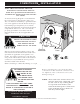
FOLLOWING ELECTRICAL
CONNECTION, THE FAN
MUST ROTATE IN THE
SAME DIRECTION AS
THE ARROW LOCAT-
ED ON THE OVEN FAN
MOTOR.
THIS APPLIANCE WILL NO
T
FUNC-
TION PROPERLY AND DAMAGE CAN
OCCUR IF THE MOTOR ROTATION IS
NOT CORRECT.
Electrical
Panel
Terminal
Block
Electrical
Connection
MOTOR
with
Rotation Direction
Ground
TO CHANGE MOTOR DIRECTION,
EXCHANGE TWO OF THE
INCOMING PHASES.
ANSI/NSF4
COMBITHERM
®
INSTALLATION
LISTED
COOKING APPLIANCE
584M