Cooking & Holding Oven Electronic Control Model: 500-TH/III 750-TH/III 1000-TH/III 1200-TH/III 1200-TH/III 1000-TH/III • INSTALLATION • OPERATION • MAINTENANCE 500-TH/III 750-TH/III W164 N9221 Water Street • P.O. Box 450 • Menomonee Falls, Wisconsin 53052-0450 USA PHONE: 262.251.3800 • 800.558.8744 USA / CANADA FAX: 262.251.7067 • 800.329.8744 U . S . A . www.alto-shaam.com printed in u.s.a.
Delivery.............................................................................. 1 Unpacking.......................................................................... 1 Safety Procedures and Precautions.................................... 2 Sanitation Sanitation/Food Safety................................................ 23 Internal Food Product Temperatures........................... 23 Installation Installation Requirements.............................................. 3 Clearance Requirements....
DELIVERY UNPACKING This Alto-Shaam appliance has been thoroughly tested and inspected to ensure only the highest quality unit is provided. Upon receipt, check for any possible shipping damage and report it at once to the delivering carrier. See Transportation Damage and Claims section located in this manual. This appliance, complete with unattached items and accessories, may have been delivered in one or more packages.
SAFETY PROCEDURES AND PRECAUTIONS Knowledge of proper procedures is essential to the safe operation of electrically and/or gas energized equipment. In accordance with generally accepted product safety labeling guidelines for potential hazards, the following signal words and symbols may be used throughout this manual. DANGER Used to indicate the presence of a hazard that WILL cause severe personal injury, death, or substantial property damage if the warning included with this symbol is ignored.
INSTALLATION DANGER IMPROPER INSTALLATION, ALTERATION, ADJUSTMENT, SERVICE, OR MAINTENANCE COULD RESULT IN SEVERE INJURY, DEATH, OR CAUSE PROPERTY DAMAGE. READ THE INSTALLATION, OPERATING AND MAINTENANCE INSTRUCTIONS THOROUGHLY BEFORE INSTALLING OR SERVICING THIS EQUIPMENT. CAUTION TO PREVENT PERSONAL INJURY, CAUTION METAL PARTS OF THIS EQUIPMENT BECOME EXTREMELY HOT WHEN IN OPERATION. TO AVOID BURNS, ALWAYS USE HAND PROTECTION WHEN OPERATING THIS APPLIANCE.
INSTALLATION SITE INSTALLATION 21" (532mm) 28-1/2" (724mm) 29-7/8" (758mm) with optional bumper 44-1/16" (1118mm) 58-1/4" (1479mm) 500-TH/III Shown with optional bumper Pass-Through Design 21-15/16" (556mm) 26-11/16" (678mm) 19-3/8" (492mm) 12-3/16" (310mm) 28-1/4" (716mm) Electrical Connection Elec.
INSTALLATION SITE INSTALLATION 28-5/8" (726mm) 34-7/8" (886mm) 56-15/16" (1445mm) 79" (2006mm) 750-TH/III 34" (864mm) Shown with optional bumper Pass-Through 31-3/4" (805mm) 30-7/8" (784mm) Electrical Connection (Pass-Through) 26-5/8" (676mm) (electrical connection) 14-3/4" (373mm) 28-1/4" (717mm) 33-1/2" (851mm) with 3-1/2" casters* 27" (686mm) 25-3/4" (654mm) 26-15/16" (683mm) *31-13/16" (807mm) - with optional 2-1/2" casters *35-1/4" (894mm) - with optional 5" casters *34-7/16" (874mm)
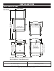
INSTALLATION SITE INSTALLATION 1000-TH/III 25-1/16" (636mm) 12-9/16" (318mm) 51-1/4" (1302mm) 53-5/8" (1361mm) Electrical Connection with optional bumper 34-1/2" (876mm) 34" (864mm) Pass-Through Design 31-3/4" (805mm) 14-1/2" (367mm) 37-11/16" (957mm) Elec.
INSTALLATION SITE INSTALLATION 1200-TH/III 72-3/4" (1847mm) 53-5/8" (1361mm) with optional bumper 51-5/8" (1310mm) 34-1/2" (876mm) with optional bumper 25-1/16" (636mm) with optional bumper Pass-Through Design 32-1/4" (819mm) 68-13/16" (1747mm) Electrical Connection (Pass-Through) 23-1/2" (596mm) 72-15/16" (1852mm) to Electrical Connection 15-1/4" (387mm) 7" (177mm) 75-3/4" (1924mm) with 5" (127mm) Casters* 22-9/16" (573mm) 24-1/8" (613mm) *74-3/8" (1889mm) - with optional 3-1/2" (89mm) cas
INSTALLATION OPTI O NS AN D ACCESSORIES Bumper, Full Perimeter ( not available with 2-1/2" casters ) Carving Holder prime rib steamship ( cafeteria ) round Casters - 2 rigid , 2 swivel w / brake 5" (127mm) 3-1/2" (89mm) 2-1/2" (64mm) Door Lock with Key Drip Pan 1-7/16" (37mm) 1-11/16" (43mm) standard with drain 1-7/8" (48mm) without drain , 1-7/16" (37mm) without drain , 1-7/8" (48mm) extra deep , 4" (102mm) standard with drain standard with drain Legs, 6" (152mm), Stemmed ( set Pan Grid, Wir
INSTALLATION STACKING INSTRUCTIONS 1) If the two appliances were shipped together from the factory, the top unit will have the casters already removed. A stacking kit will be included with the shipment. If casters need to be removed: lay the unit on its back, and remove the set screw on each caster. Pull the casters out of the unit. 2) While appliance is laid on its back, insert one stacking post in each of the four corners of the upper unit.
INSTALLATION SITE INSTALLATION A number of adjustments are associated with initial installation and start-up. It is important that these adjustments be conducted by a qualified service technician. Installation and start-up adjustments are the responsibility of the dealer or user. These adjustments include but are not limited to thermostat calibration, door adjustment, leveling, electrical hook-up and installation of optional casters or legs.
INSTALLATION SITE INSTALLATION DRIP TRAY INSTALLATION INSTRUCTIONS b d a c Item Description Qty 1 Double-Sided Tape 1 2 Drip Tray Holder 1 3 8-32 x 1/4” Phil Screw 3 4 Drip Tray 1 1. Poke holes through double-sided tape a which is attached to the back of drip tray holder b. 2. Remove backing on double-sided tape a. 3. Put screws c through holes and attach drip tray holder b to unit. 4.
INSTALLATION ELECTRICAL CONNECTION The appliance must be installed by a qualified service technician. The oven must be properly grounded in accordance with the National Electrical Code and applicable local codes. Plug the unit into a properly grounded receptacle ONLY, positioning the unit so that the plug is easily accessible in case of an emergency. Arcing will occur when connecting or disconnecting the unit unless all controls are in the “OFF” position.
INSTALLATION ELECTRICAL CONNECTION EL EC T RIC A L - 500-TH/III voltage phase cycle / hz amps kW 120 1 60 16.0 1.92 208-240 (agcy) 1 at 208 1 at 240 1 230 1 60 60 60 11.2 10.6 12.2 2.70 2.20 2.93 50 12.0 2.75 cord & nema plug 5-20 p 20A-125 v plug cord , no plug cee 7/7 220-230 v plug EL EC T RIC A L - 750-TH/III voltage phase 208-240 (agcy) 1 at 208 1 at 240 1 230 ( agcy ) 1 cycle / hz amps kW 60 60 60 15.8 14.6 16.9 3.80 3.04 4.05 50 14.3 3.
OPERATING INSTRUCTIONS USER SAFETY INFORMATION CAUTION METAL PARTS OF THIS EQUIPMENT BECOME EXTREMELY HOT WHEN IN OPERATION. TO AVOID BURNS, ALWAYS USE HAND PROTECTION WHEN OPERATING THIS APPLIANCE. The Alto-Shaam cook and hold oven is intended for use in commercial establishments by qualified operating personnel where all operators are familiar with the purpose, limitations, and associated hazards of this appliance.
OPERATING INSTRUCTIONS Power ON Indicator gf h i j k b c d e l m upper a n lower a p o CONTROL FEATURES 1. On/Off Key The on/off control system key operates the functions of the control panel. If there is any power loss during operation, the on/off indicator light will flash. To clear, push key and release. 2. Cook Key — Temperature range 2 00° to 325°F (93° to 162°C) Used to select cooking mode and to review the cook temperature setting. 3.
OPERATING INSTRUCTIONS O P E R A T I N G FEAT U RES & F U N C T I ON S To stop an operation at any time — Press and hold the Start Key until the control beeps for two seconds, indicating the operation has been cancelled. The oven will remain in a power-on state. To turn oven control panel off — Press and hold the On/Off Key until the oven beeps. The On/Off indicator light will go out. Door open indicator — Display will flash “door” and a triple beep will alert the user.
OPERATING INSTRUCTIONS Cook/Hold Instructions Press and release control On/O ff key. The oven will beep for one second and power to the unit will be indicated by an illuminated green indicator light located in the upper left corner of the O n /O ff key. The oven will begin operating in the hold mode. The amber H old indicator will be illuminated and the last set hold temperature will be displayed. To set Cook temperature — Press Cook Key.
OPERATING INSTRUCTIONS Programming a Preset Select the product to be programmed and begin programming with the oven control power O ff . Press and release control O n/O ff key. The oven will beep for one second and power to the unit will be indicated by an illuminated green indicator light located in the upper left corner of the O n /O ff key. The oven will begin operating in the hold mode. The amber H old indicator will be illuminated and the last set hold temperature will be displayed.
OPERATING INSTRUCTIONS USER OPTIONS Lock Indicator Preset Lock P reset Keys Lock and Unlock Control Panel Lock and Unlock P reset Keys A through H can be locked in order to prevent storing, altering or erasing a program. The control panel can be locked at any time in order to prevent inadvertent or accidental setting changes. To lock the P reset Keys, press and hold the “I” Key until the oven beeps. Release the “I” key. The green indicator on the “I” key will illuminate.
OPERATING INSTRUCTIONS General Holding Guideline HOLDING TEMPERATURE RANGE Chefs, cooks and other specialized food service personnel employ varied methods of cooking. Proper holding temperatures for a specific food product must be based on the moisture content of the product, product density, volume, and proper serving temperatures. Safe holding temperatures must also be correlated with palatability in determining the length of holding time for a specific product.
AER EI V A DI NC ACNE I N G C L E A N I N G A N D P RC EV NT E N MA T ELNE AN PROTECTING STAINLESS STEEL SURFACES It is important to guard against corrosion in the care of stainless steel surfaces. Harsh, corrosive, or inappropriate chemicals can completely destroy the protective surface layer CLEANING AGENTS Use non-abrasive cleaning products designed for use on stainless steel surfaces. Cleaning agents must be chloride-free compounds and must not contain quaternary salts.
CARE AND CLEANING EQUIPME NT CARE Under normal circumstances, this oven should provide you with long and trouble free service. There is no preventative maintenance required, however, the following Equipment Care Guide will maximize the potential life and trouble free operation of this oven. The cleanliness and appearance of this equipment will contribute considerably to operating efficiency and savory, appetizing food. Good equipment that is kept clean works better and lasts longer. CLEAN DAILY 1.
SANITATION Food flavor and aroma are usually so closely related that it is difficult, if not impossible, to separate them. There is also an important, inseparable relationship between cleanliness and food flavor. Cleanliness, top operating efficiency, and appearance of equipment contribute considerably to savory, appetizing foods. Good equipment that is kept clean, works better and lasts longer. Most food imparts its own particular aroma and many foods also absorb existing odors.
SERVICE TRO UB L E S H O O T I N G Error Code Description Possible Cause E-10 Cavity air sensor shorted Cavity air sensor reading < 5°F. Verify sensor integrity. See sensor test instructions below. E-11 Cavity air sensor open Cavity air sensor reading > 517°F. Verify sensor integrity. See sensor test instructions below. E-20 Product probe is shorted Product probe reading < 5°F. Verify sensor integrity. Oven will cook in time only See sensor test instructions below.
SERVICE This section is provided for the assistance of qualified technicians only and is not intended for use by untrained or unauthorized service personnel. If your Alto-Shaam® unit is not operating properly, check the following before calling your Authorized Alto-Shaam Service Agent: * Check the power flow to the unit. Plug in outlet? Circuit breaker switch at back of unit turned on? Do not attempt to repair or service the Cook and Hold unit beyond this point.
SERVICE A E X TE R IOR S E R V I C E V I E W 750-TH/III Shown 12 28 27 34 7 22 15 32 36 26 1 9 11 A-A 25 10 A A 35 37 38 17 20 2 4 30 16 31 24 8 14 21 34 6 5 23 29 31 3 P art numbe rs a nd dra wings ar e s ubjec t t o c hange w i t h o u t n o t i c e . pg .
SERVICE E X TE R IOR S E R V I C E V I E W - PART S L I ST A MODEL > IT EM D ESC R I PT I O N 5 0 0 -T H / I I I 750-TH/III 1000-TH/III PART NO. QTY PART NO. QTY PART NO.
SERVICE E X TE R IOR S E R V I C E V I E W B 1200-TH/III 29 40 31 7 13 28 24 12 11 27 8 10 43 16 13 A-A 15 1 41 42 37 31 A A 44 22 38 9 3 17 18 33 40 30 25 35 4 23 19 14 6 34 35 26 21 P art numbe rs a nd dra wings ar e s ubjec t t o c hange w i t h o u t n o t i c e . pg .
SERVICE E X TE R IOR S E R V I C E V I E W - PART S L I ST B MO D E L > 1 2 0 0 - T H / I I I ITEM DESCRIPTION PART NO. QTY ITEM DESCRIPTION PART NO. QTY 1 GUARD, SENSOR 1493 2 24 GASKET ASSY, BONNET GS-23622 1 2* PROBE HOLDER 13239 1 25 HANDLE, OFFSET MAG.
SERVICE E LE CTR ONI C C O MP O N E N TS C 1200-TH/III Shown 7 2 18 17 20 21 43 44 34 6 26 4 39 9 40 29 33 16 5 45 19 37 38 14 36 25 35 1 23 46 28 47 3 10 24 30 11 8 12 P art numbe rs a nd dra wings ar e s ubjec t t o c hange w i t h o u t n o t i c e . pg .
SERVICE E LE CTR ONI C C O MP O N E N TS PART S LI ST C M O D EL > ITE M DE SC R I PT I O N 5 00 -T H / I I I 750-TH/III PAR T N O . QTY PART NO. 1 0 0 0 -T H / I I I 1 200- TH/I I I QTY PART NO. QTY P A R T NO.
pg .
TH/III installation / operation / service manual pg .
pg .
TH/III installation / operation / service manual pg .
pg .
TH/III installation / operation / service manual pg .
pg .
TRANSPORTATION DAMAGE and CLAIMS 1. 2. 3. 4. 5. 6. 7. 8. All Alto-Shaam equipment is sold F.O.B. shipping point, and when accepted by the carrier, such shipments become the property of the consignee. Should damage occur in shipment, it is a matter between the carrier and the consignee. In such cases, the carrier is assumed to be responsible for the safe delivery of the merchandise, unless negligence can be established on the part of the shipper.