Rotisserie Electric Models: AR-7EVH ELECTRIC ROTISSERIE WITH VENTLESS HOOD • INSTALLATION • OPERATION • MAINTENANCE W164 N9221 Water Street • P.O. Box 450 • Menomonee Falls, Wisconsin 53052-0450 USA PHONE: 262.251.3800 • 800.558.8744 USA / CANADA FAX: 262.251.7067 • 800.329.8744 U . S . A . www.alto-shaam.com printed in u.s.a.
Delivery..................................................................... 1 Unpacking................................................................. 1 Safety Procedures and Precautions........................... 2 Installation Site Installation..................................................... 3 Leveling................................................................ 3 Clearance Requirements...................................... 3 Sound Pressure Levels.........................................
DELIVERY UNPACKING This Alto-Shaam appliance has been thoroughly tested and inspected to ensure only the highest quality unit is provided. Upon receipt, check for any possible shipping damage and report it at once to the delivering carrier. See Transportation Damage and Claims section located in this manual. This appliance, complete with unattached items and accessories, may have been delivered in one or more packages.
SAFETY PROCEDURES AND PRECAUTIONS Knowledge of proper procedures is essential to the safe operation of electrically and/or gas energized equipment. In accordance with generally accepted product safety labeling guidelines for potential hazards, the following signal words and symbols may be used throughout this manual. DANGER Used to indicate the presence of a hazard that WILL cause severe personal injury, death, or substantial property damage if the warning included with this symbol is ignored.
INSTALLATION SITE INSTALLATION DANGER CAUTION METAL PARTS OF THIS EQUIPMENT BECOME EXTREMELY HOT WHEN IN OPERATION. TO AVOID BURNS, ALWAYS USE HAND PROTECTION WHEN OPERATING THIS APPLIANCE. IMPROPER INSTALLATION, ALTERATION, ADJUSTMENT, SERVICE, OR MAINTENANCE COULD RESULT IN SEVERE INJURY, DEATH, OR CAUSE PROPERTY DAMAGE. DANGER READ THE INSTALLATION, OPERATING AND MAINTENANCE INSTRUCTIONS THOROUGHLY BEFORE INSTALLING OR SERVICING THIS EQUIPMENT.
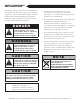
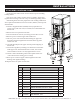
4" (102mm) TURKEY SPIT CORD LENGTH plug): CORD LENGTH (no(no plug): 6-1/2' (1,981mm) 6-1/2' (1,981mm) side view - ANGLED SPITS ( OPTIONAL ): ( UP TO 3 SPITS CAN BE USED ) 32-3/8" (823mm) 32-3/8" (823mm) ( STANDARD ): ( UP TO 7 SPITS CAN BE USED ) Up to twenty-one (21) 3-1/2 lb chickens (1,6 kg) Up to twenty-eight (28) 2-1/2 to 3 lb chickens (1,1 to 1,4 kg) 98 lb (44 kg) Electrical Connection 20-5/16" (516mm) solid back Electrical Electrical Connection Connection CORD LENGTH (no plug): 6-1/2'
INSTALLATION ELECTRICAL CONNECTION The appliance must be installed by a qualified service technician. The oven must be properly grounded in accordance with the National Electrical Code and applicable local codes. E LE C T R I C A L DANGER To avoid electrical shock, this appliance MUST be adequately grounded in accordance with local electrical codes or, in the absence of local codes, with the current edition of the National Electrical Code ANSI/ NFPA No. 70.
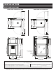
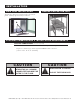
INSTALLATION DRIP TRAY INSTALLATION GREASE COLLECTION UNIT Attach tray using two carriage bolts (A) in base panel. Lift tray up and away to remove. A STACKING COMBINATIONS & INSTALLATION REQUIREMENTS S T A C KIN G C O MBIN A T IO N S ( FACTORY INSTALLED ) AR-7EVH rotisserie with ventless hood over AR-7H companion holding cabinet Requires 6" (152mm) legs with flanged feet 5001761 bolted to the floor. [ OVERALL HEIGHT : 90-13/16" (2307mm)] CAUTION STACKING APPLICATIONS OUTSIDE THE U.S.
INSTALLATION STACKING INSTRUCTIONS A rotisserie with ventless hood can be stacked on top of a matching holding cabinet. Only screws, lock washers, and hex nut are required to fasten units together when stacking a rotisserie on top of a matching holding cabinet. All fastening holes have been prepunched. The stacking combination also requires the minimum clearance of 6-inches (152mm) at the top, back and both sides. 1.
INSTALLATION OPTIONS & ACCESSORIES DE S CRIPT IO N P A RT NO. DOOR HANDLE DRIP PAN, stainless non - control side steel FEET, RUBBER, 2" (51mm) without drain for counter top units only ( not available on models built for GREASE COLLECTION UNIT US ce only 5001614 5012800 LEGS assembly , 6" (152mm) assembly , flanged feet , 6" (152mm) ( required MULTI-PURPOSE WIRE BASKET (.
OPERATING INSTRUCTIONS START-UP VENTLESS HOOD CONTROL IDENTIFICATION 1. B efore operating the unit, become familiar with the operation of the controls. Read this manual carefully and retain it for future reference. 2. E nsure the filters inside the hood are correctly in place and the door is closed. 3. T urn on the hood by turning the power switch a to the “I” position • N ote that the fan indicator light b will illuminate while running. 4.
OPERATING INSTRUCTIONS ROTISSERIE CONTROL IDENTIFICATION Cook Cycle Indicator Bar Preheat Indicator Bar Cook Time Indicator Bar 1 Cook Time Indicator Bar 2 Holding Indicator Bar Product Ready Indicator Bar UP Arrow Key LED Display DOWN Arrow Key FOR 2-STEP COOKING TIME Cook Temperature Indicator Bar 1 Cook Temperature Indicator Bar 2 Preset Key Lock Indicator Bar FOR 2-STEP COOKING Hold Key ON/OFF Power Key Time Key Cook Key Start Key Indicator Light Preset Menu Program Keys OPTION Preset Pro
M N- 28907 ( R e v 0 ) • A R -7 E VH El e c tri c R oti sseri e w i th V entl ess H ood Operati on & C are Manu al • 11 NOT REQUIRED 160°F (71°C) NOT REQUIRED 185°F (85°C) COOK TI ME 2 HOL D TE MP B ROW NI NG TI ME F I NA L IN TE RNA L TE MP (20 min for long-term holding) 30 minutes NOT REQUIRED C OOK TE MP 2 C OOK TIM E 1 425°F (218°C) C OOK TE MP 1 185°F (85°C) 5 minutes 160°F (71°C) NOT REQUIRED 45 minutes NOT REQUIRED 400°F (204°C) 180°F (82°C) NOT REQUIRED 165°F (74°C) 15 minu
OPERATING INSTRUCTIONS COOKING INTRUCTIONS Press the ON/OFF key. 1. The on/off indicator light will illuminate. 2. The display will show the last set holding temperature. 3. The hold indicator will illuminate. 4. The rotisserie will begin to preheat to the holding temperature shown in the display. Press the COOK key. 1. The COOK and the TIME underscore lights will alternately illuminate. 2. The display will indicate the last set cooking temperature when the COOK underscore light is illuminated.
OPERATING INSTRUCTIONS HOLD ONLY INSTRUCTIONS Hold with rotisserie can be set in the power on hold mode or if the operator wants to stop a cooking procedure but continue holding with rotisserie. Press the ON/OFF key. 1. The on/off indicator light will illuminate. 2. The display will show the last set holding temperature. 3. The hold indicator will illuminate. 4. The rotisserie will begin to preheat to the holding temperature shown in the display. Press the HOLD key. 1.
OPERATING INSTRUCTIONS ADDITIONAL BROWNING FEATURE The control allows the operator to set a specific period of time for additional browning between the end of the COOK TIME and the illumination of the PRODUCT READY BAR at the end of the cooking cycle. Browning time is to be added during initial product programming. Press the HOLD key. 1. The HOLD underscore light will illuminate. 2. The display will indicate the last browning time.
OPERATING INSTRUCTIONS PRESET MENU KEY OPTION The Alto-Shaam rotisserie provides the operator with the ability to set as many as seven cooking programs. Each cooking program can be preset to include all cooking and holding functions. Cooking programs are stored and recalled using the P RESET Keys labeled 1 through 7. PROGRAMMING A COOKING PROGRAM: With the rotisserie oven in the “ OFF ” position, determine the food product procedure to be programmed. Press and release control ON / OFF key.
OPERATING INSTRUCTIONS ATTEN T I ON CHICKEN, WHOLE After programming a specific product into memory on a preset key number, it is suggested the product be identified by inserting a label in the Program Menu Identification Card Slot. C H I C K E N , Q U A R T ERS TURKEY BREAST PORK RIBS PORK LOIN LAMB LEGS TO ERASE A PRESET To erase a preset, the oven must be in either the power-up hold mode or in the preheat mode. The oven cannot be in a cook or automatic hold.
OPERATING INSTRUCTIONS PRODUCT LOADING STANDARD SPITS Each of the seven rotisserie spits includes two welded prongs on the square end and one welded, ridged prong on the tapered end. Insert the two-prong, square end into the two holes indicated on the disk assembly drive wheel in the drawing. Insert the tapered, ridged-prong end into the top hole indicated on the opposite side and maneuver until the ridge catches in the hole.
OPERATING INSTRUCTIONS PRODUCT LOADING STANDARD SPIT Insert whole chickens with the legs toward the square end of the spit. Load up to 3, 3-1/2 lb (1,6 kg) chickens per spit for a total of 21 chickens or 4, 2-1/2 lb (1,1 kg) chickens for a total of 28 whole chickens. PIERCING SPIT ( OPTION ) The optional piercing spit (Item SI-25729) will accommodate 4, 2-1/2 lb (1,1 kg) to 3-1/2 lb (1,6 kg) whole chickens per spit. BASKET SPIT ( OPTION ) Basket spits (Item BS-26019 with .
OPERATING INSTRUCTIONS GREASE COLLECTION PROCEDURES 1 2 3 4 5 6 1. Open oven door and pull bottom grease tray forward 4. by pulling on the handle. Pull tray forward only until it engages with the automatic stop mechanism. DO NOT pull tray out farther than mechanism will allow. 2. Position rolling grease collection unit in front of oven by pulling it forward. Turn and loosen black release knob to extend the telescoping funnel upward. Ensure 5. top funnel cup is directly under the grease tray spout.
OPERATING INSTRUCTIONS GREASE COLLECTION PROCEDURES 7 8 10 9 11 7. Turn and loosen black release knob and gently guide the telescoping funnel downward. 8. Telescoping funnel should be lowered to the level at which it stops without applying force. When properly lowered the funnel will fit under the oven unit. 10. Check grease level in the rolling grease collection unit after every drain cycle. Using handle at front of rolling grease collection unit, lift lid of unit to observe grease level.
CARE AND CLEANING CLEANING AND PREVENTATIVE MAINTENANCE PROTECTING STAINLESS STEEL SURFACES It is important to guard against corrosion in the care of stainless steel surfaces. Harsh, corrosive, CLEANING AGENTS Use non-abrasive cleaning products designed for use on stainless steel surfaces. Cleaning agents must be chloride-free compounds and must not or inappropriate chemicals contain quaternary salts.
CARE AND CLEANING HOOD CLEANING & MAINTENANCE To ensure optimum performance from the ventless hood, it is important to establish and maintain a regular cleaning and maintenance schedule. Use of the cleaning and maintenance reminder form is highly recommended. Note: If cleaning is not preformed according to the instructions a fire may occur. Access to the internal components, safety switches, filters, etc., are gained by opening the access door.
CARE AND CLEANING HOOD CLEANING & MAINTENANCE When performing replacement of filters at minimum 3 month OR when heavy contamination is found (which ever happens first), it is recommended that the exhaust tube be cleaned. To clean insert a flexible wire brush with the recommended cleaning solution as specified in this manual into both sides of the exhaust tube and scrub until any grease buildup is removed. NOTE: liquid cleaner may be sprayed into the exhaust tube as needed before applying the brush.
CARE AND CLEANING ROTTISSERIE CLEANING & MAINTENANCE EQUIPMENT CARE Under normal circumstances, this oven should provide you with long and trouble free service. There is no preventative maintenance required, however, the following Equipment Care Guide will maximize the potential life and trouble free operation of this oven. The cleanliness and appearance of this equipment will contribute considerably to operating efficiency and savory, appetizing food.
CARE AND CLEANING DAILY ROTTISSERIE GASKET CLEANING It is important to prolong the life of the oven gasket by cleaning this item on a daily basis. The acids and related compounds found in fat, particularly chicken fat, will weaken the composition of the gasket unless cleaned on a daily basis. Routine cleaning will help protect the composition of the gasket from deterioration caused by acidic foods. After allowing the oven to cool, remove pull-out gasket and wash in hot, soapy water.
CARE AND CLEANING CHECK OVERALL CONDITION OF THE ROTISSERIE ONCE A MONTH Check for physical damage and loose screws. Correct any problems before they begin to interfere with the operation of the oven. CAUTION DANGER BRU S NO ST E EL P A DS NO NO IR E S WARRANTY BECOMES VOID IF APPLIANCE IS FLOODED W HE SEVERE DAMAGE OR ELECTRICAL HAZARD COULD RESULT. S RS AT NO TIME SHOULD THE INTERIOR OR EXTERIOR BE STEAM CLEANED, HOSED DOWN, OR FLOODED WITH WATER OR LIQUID SOLUTION OF ANY KIND.
SERVICE TROUBLESHOOTING GUIDE Code Description Possible Cause E-30 Cavity air sensor reading < 5°F. Verify sensor integrity. See sensor test instructions below. Cavity air sensor reading > 517°F. Verify sensor integrity. Cavity air sensor open See sensor test instructions below. Product probe is shorted Product probe reading < 5°F. Verify sensor integrity. Oven will cook in time only See sensor test instructions below. Product probe is open Product Probe reading > 517°F. Verify sensor integrity.
SERVICE VENTLESS HOOD, FINAL FLOOR (RIGHT HAND SHOWN) 8 9 6 1 5 2 7 4 3 10 11 12 38 39 37 36 34 35 13 14 33 27 32 26 31 28 30 15 23 10 25 22 10 24 4 VENTLESS HOOD, ELECTRICAL ASSEMBLY (close-up - 5008919) 29 21 20 16 19 18 17 P art numbe rs a nd dra wings ar e s ubjec t t o c hange w i t h o u t n o t i c e .
SERVICE VENTLESS HOOD, FINAL FLOOR & ELECTRICAL PARTS LIST *not shown IT EM D ES C R I P T I O N PART NO.
SERVICE VENTLESS HOOD, FULL ASSEMBLY (RH, CURVED DOOR, PASS THROUGH SHOWN) 5 2 3 4 6 7 9 8 1 9 *not shown ITE M MO D E L > D ESCR I PT I O N C U R VE D D O O R FLA T DOOR* PART NO. QTY P A R T NO.
SERVICE ROTISSERIE, BULB REPLACEMENT INSTRUCTIONS A To Replace Bulbs: A. Remove four screws holding glass light cover (CV-26607) and gasket (GS-26609) in place, taking care to not let the glass cover (GL-26608) fall into the oven. B. Pull bulb out. C. Push replacement bulb (LP-34213) in place. D. Re-install glass cover and gasket, securing with four screws removed in step one. B&C CAUTION DO NOT HANDLE NEW BULB WITH BARE HANDS. WHITE COTTON GLOVES SHOULD BE WORN WHEN REPLACING BULBS.
SERVICE 15 16 17 34 39 27 P art numbe rs a nd dra wings ar e s ubjec t t o c hange w i t h o u t n o t i c e .
SERVICE ROTISSERIE, FINAL FLOOR PARTS LIST *not shown MO D E L > ITE M D ESC R I PT I O N C U R VE D D O O R FLA T DOOR PART NO. QTY P A R T NO. QTY 1 SPOT ASSEMBLY, TOP PANEL 5009718 1 5009718 1 2 INSULATION, 1" X 4' X 25' #6, RT2300 (4.
SERVICE ROTISSERIE, FINAL FLOOR PARTS LIST (continued) *not shown ITE M MO D E L > D ESC R I PT I O N C U R VE D D O O R FLAT DOOR PART NO. QTY P A R T NO.
SERVICE ROTISSERIE, FULL ASSEMBLY (CURVED DOOR, FLAT BACK SHOWN) 10 9 12 11 16 2 3 14 7 13 8 15 17 6 4 18 ROTISSERIE, DOOR ASSEMBLY 1 (CURVED DOOR, CONTROL SIDE SHOWN) 21 5 20 19 P art numbe rs a nd dra wings ar e s ubjec t t o c hange w i t h o u t n o t i c e .
SERVICE ROTISSERIE, FULL ASSEMBLY PARTS LIST *not shown MO D E L > ITE M D ESC R I PT I O N C U R VE D D O O R FLA T DOOR PART NO. QTY P A R T NO.
SERVICE ROTISSERIE, INTERIOR VIEW 1 2 6 4 3 5 7 MO D E L > IT EM D ESC R I PT I O N C U R VE D D O O R FLA T D O O R PART NO. QTY PART NO.
SERVICE ROTISSERIE, ELECTRICAL SERVICE VIEW 1 13 2 12 3 4 11 5 6 10 9 7 8 *not shown IT EM MO D E L > D ESCR I PT I ON C U R VE D D O O R PART NO. QTY FLA T D O O R PART NO.
SERVICE ROTISSERIE, REPLACEMENT OF GLASS DOOR (FLAT DOOR SHOWN) 1 “A” A 8 DETAIL A 7 2 B “B” 6 3 DETAIL B 4 DOOR REPLACEMENT: STEP 1: REMOVE TOP PIN (PI-26350) FROM BRACKET "A" USING A SMALL SCREWDRIVER. STEP 2: ASSEMBLE DOOR ON UNIT WITH SPACERS AS SHOWN (DETAIL B). STEP 3: MAKE CERTAIN DOOR IS ALIGNED AND REINSERT TOP PIN. WARNING DO NOT ATTEMPT TO REMOVE THE DOOR WITHOUT ASSISTANCE. THE DOOR IS EXTREMELY HEAVY, WILL BE DAMAGED IF DROPPED, AND MAY CAUSE SERIOUS INJURY.
SERVICE ROTISSERIE, STAINLESS STEEL BACK PANEL (5006214) “A” 1 “B” 2 “A” “A” 5 4 3 6 Installation instructions: 7 STEP 1: REMOVE GASKET AND ALL SCREWS ON INSTALLATION SIDE. STEP 2: INSTALL 1006652 USING (16) SC-25849 SCREWS IN LOCATIONS MARKED “A.” 8 STEP 3: INSTALL 1006746 INTO 1006652 USING (4) SC-27843 SCREWS, (8) SC-2459 SCREWS AND (4) 1002822 SPACERS. STEP 4: SEAL COMPLETE PERIMETER OF OPENING WITH SILICONE “B”.
SERVICE GREASE COLLECTION UNIT (5012271) 11 6 7 11 12 5 8 9 2 10 3 I T EM DESCRIPTION 1 4 PART NO.
AR- 7EVH Elect r ic Rot isser ie wit h Vent less Hoo d O p e ra t io n & Ca re Ma n u a l • 4 2
AR- 7EVH Elect r ic Rot isser ie wit h Vent less Hoo d O p e ra t io n & Ca re Ma n u a l • 4 3
AR- 7EVH Elect r ic Rot isser ie wit h Vent less Hoo d O p e ra t io n & Ca re Ma n u a l • 4 4
AR- 7EVH Elect r ic Rot isser ie wit h Vent less Hoo d O p e ra t io n & Ca re Ma n u a l • 4 5
TRANSPORTATION DAMAGE and CLAIMS 1. 2. 3. 4. 5. 6. 7. 8. All Alto-Shaam equipment is sold F.O.B. shipping point, and when accepted by the carrier, such shipments become the property of the consignee. Should damage occur in shipment, it is a matter between the carrier and the consignee. In such cases, the carrier is assumed to be responsible for the safe delivery of the merchandise, unless negligence can be established on the part of the shipper.