Hot Holdi ng Ro t iss eri e C omp ani on Models: AR-7H AR-7H MANUAL CONTROL ELECTRONIC CONTROL SHOWN WITH PASS-THROUGH OPTION • INSTALLATION • OPERATION • MAINTENANCE W164 N9221 Water Street • P.O. Box 450 • Menomonee Falls, Wisconsin 53052-0450 USA PHONE: 262.251.3800 • 800.558.8744 USA / CANADA FAX: 262.251.7067 • 800.329.8744 U . S . A . www.alto-shaam.com PRINTED IN U.S.A.
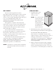
DELIVERY U N PA C K I N G This Alto-Shaam appliance has been thoroughly tested and inspected to insure only the highest quality unit is provided. Upon receipt, check for any possible shipping damage and report it at once to the delivering carrier. See Transportation Damage and Claims section located in this manual. This appliance, complete with unattached items and accessories, may have been delivered in one or more packages.
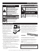
SAFETY PROCEDURES AND PRECAUTIONS Knowledge of proper procedures is essential to the safe operation of electrically and/or gas energized equipment. In accordance with generally accepted product safety labeling guidelines for potential hazards, the following signal words and symbols may be used throughout this manual. DANGER Used to indicate the presence of a hazard that WILL cause severe personal injury, death, or substantial property damage if the warning included with this symbol is ignored.
I N S TA L L AT I O N DANGER CAUTION IMPROPER INSTALLATION, ALTERATION, ADJUSTMENT, SERVICE, OR MAINTENANCE COULD RESULT IN SEVERE INJURY, DEATH OR CAUSE PROPERTY DAMAGE. READ THE INSTALLATION, OPERATING AND MAINTENANCE INSTRUCTIONS THOROUGHLY BEFORE INSTALLING OR SERVICING THIS EQUIPMENT. CAUTION METAL PARTS OF THIS EQUIPMENT BECOME EXTREMELY HOT WHEN IN OPERATION. TO AVOID BURNS, ALWAYS USE HAND PROTECTION WHEN OPERATING THIS APPLIANCE.
SIDE VIEW 38-1/8" (968mm) 37-1/8" (942mm) 25-1/2" (649mm) 32" (813mm) WITH SOLID BACK WITH PASS-THROUGH OPTION CL 34-1/2" (876mm) 25-1/2" (646mm) WITH SOLID BACK WITH PASS-THROUGH OPTION 32-1/16" (816mm) 32-1/16" (814mm) WITH PASS-THROUGH OPTION 6 SIDE VIEW 6-1/4" (159mm) 32-7/16" (824mm) FRONT VIEW A R -7H H ot H ol di ng R oti s serie Companion Operation & Care Manual • 4 WITH PASS-THROUGH OPTION PASS-THROUGH OPTION 87-5/8" (2224mm) 61-3/16 (1554mm) WITH 58-3/16" (1477mm) WITH SOLID BA
I N S TA L L AT I O N ELECTRICAL CONNECTION The appliance must be installed by a qualified service technician. The oven must be properly grounded in accordance with the National Electrical Code and applicable local codes. DANGER To avoid electrical shock, this appliance MUST be adequately grounded in accordance with local electrical codes or, in the absence of local codes, with the current edition of the National Electrical Code ANSI/NFPA No. 70.
I N S TA L L AT I O N S TA C K I N G C O M B I N AT I O N S & I N S TA L L AT I O N R E Q U I R E M E N T S AR-7H companion holding cabinet over AR-7H companion holding cabinet S TA C KIN G C O M BIN ATIO N S ( FACTORY INSTALLED ) Requires 6" (152mm) leg assembly 5001414 or 5" (127mm) casters 4007 and stacking assembly 5009711 for applications within the United States. Applications outside the U.S. requires 6" (152mm) legs with flanged feet 5001761 bolted to th e floor.
I N S TA L L AT I O N S TA C K I N G I N S T R U C T I O N S The holding cabinet can be stacked with an identical holding cabinet or a matching rotisserie oven in either the top or bottom position. Only screws, lock washers, and hex nut are required to fasten units together when stacking a rotisserie on top of a matching holding cabinet or a holding cabinet on top of a holding cabinet. Additional stacking hardware is required for all other combinations ( SEE PREVIOUS PAGE ).
I N S TA L L AT I O N AR-7H — OPTIONS & ACCESSORIES DESCRIPTION PART NUMBER DOOR OPTIONS DOOR HANDLE SINGLE PANE FLAT GLASS WITH HANDLE 5009591 SINGLE PANE FLAT GLASS WITHOUT HANDLE 5009815 HD-26900 FOR SINGLE PANE GLASS DOOR ON NON-CONTROL SIDE CONTROL OPTION KIT 5000886 FOR SOFTWARE DOCUMENTATION COMPUTER SOFTWARE HACCP DOCUMENTATION HACCP WITH KITCHEN MANAGEMENT REFER TO HACCP SPECIFICATION #9015 FOR APPLICABLE PART NUMBERS ASSEMBLY, 6" (152mm) 5001414 ASSEMBLY, FLANGED FEET, 6" (152m
MANUAL CONTROL IDENTIFICATION O P E R AT I N G I N S T R U C T I O N S 180 19 0 0 16 80 90 200 140 70 120 60 210 100 40 TEMPERATURE GAUGE °C 100 220 °F HEAT INDICATOR LIGHT F OFF 60 200 80 180 THERMOSTAT 0 10 16 0 140 120 ON/OFF SWITCH HEATING PROCEDURE 1. PREHEAT AT 200°F (93°C) FOR 30 MINUTES.
O P E R AT I N G I N S T R U C T I O N S ELECTRONIC CONTROL IDENTIFICATION ON/OFF KEY Press the ON/OFF key once and the power indicator light will illuminate. Press and hold the ON/OFF key until the LED display turns off (at least three seconds) and power indicator light goes out. LED DISPLAY UP DOWN ARROW KEY LOCK INDICATOR UP/DOWN ARROWS HEAT INDICATOR LIGHT ON/OFF POWER KEY The UP and DOWN arrow keys are used for a variety of settings when selecting the holding temperature.
O P E R AT I N G I N S T R U C T I O N S GENERAL HOLDING GUIDELINES Chefs, cooks and other specialized food service personnel employ varied methods of cooking. Proper holding temperatures for a specific food product must be based on the moisture content of the product, product density, volume, and proper serving temperatures. Safe holding temperatures must also be correlated with palatability in determining the length of holding time for a specific product.
AN NIITAT T A TI IOONN SA Food flavor and aroma are usually so closely related that it is difficult, if not impossible, to separate them. There is also an important, inseparable relationship between cleanliness and food flavor. Cleanliness, top operating efficiency, and appearance of equipment contribute considerably to savory, appetizing foods. Good equipment that is kept clean, works better and lasts longer.
CARE AND CLEANING CLEANING AND PREVENTIVE MAINTENANCE PROTECTING STAINLESS STEEL SURFACES It is important to guard against corrosion in the care of stainless steel surfaces. Harsh, corrosive, or inappropriate chemicals can completely destroy the protective surface layer of stainless steel. Abrasive pads, steel wool, or metal implements will abrade surfaces causing damage to this protective coating and will eventually result in areas of corrosion.
CARE AND CLEANING EQUIPMENT CARE Under normal circumstances, this cabinet should provide you with long and trouble free service. There is no preventative maintenance required, however, the following Equipment Care Guide will maximize the potential life and trouble free operation of this oven. The cleanliness and appearance of this equipment will contribute considerably to operating efficiency and savory, appetizing food. Good equipment that is kept clean works better and lasts longer.
SERVICE TROUBLESHOOTING GUIDE - ELECTRONIC CONTROL Error Code Description/Results E-10 Air Sensor Fault (shorted) Inoperative Oven E-11 Air Sensor Fault (open) Inoperative Oven E-30 Under temperature Oven will not reach set temperature E-31 Over temperature Oven will shut down E-80 EEPROM - Function data error Inoperative Oven E-82 EEPROM - Calibration data error Inoperative Oven Possible Cause Service Required Air sensor is shorted.
SERVICE DANGER DANGER LOCK-OUT OR POST B R E A K E R PA N E L U N T I L SERVICE WORK HAS BEEN COMPLETED. DISCONNECT UNIT FROM POWER SOURCE BEFORE CLEANING OR SERVICING. CAUTION DANGER ELECTRICAL CONNECTIONS MUST BE MADE BY A QUALIFIED SERVICE TECHNICIAN IN ACCORDANCE WITH APPLICABLE ELECTRICAL CODES. THIS SECTION IS PROVIDED FOR THE ASSISTANCE OF QUALIFIED SERVICE TECHNICIANS ONLY AND IS NOT INTENDED FOR USE BY UNTRAINED OR UNAUTHORIZED SERVICE PERSONNEL.
SERVICE SERVICE VIEW 2: INTERIOR SERVICE VIEW Lamp Door Gasket LP-33598 (120V) LP-33803 (208-240V) LP-33803 (230V) GS-25753 Lamp Receptacle RP-3952 (120V) RP-3952 (208-240V) RP-3955 (230V) Shelf Side Rack LEFT- HAND 5001901 SH-24720 Side Rack RIGHT- HAND 5004361 A R -7H H ot H ol di ng R oti s serie Companion Operation & Care Manual • 17
SERVICE S E R V I C E V I E W 3 : S I N G L E PA N E F L AT G L A S S D O O R WA R N I N G DOOR REPLACEMENT: STEP 1: REMOVE TOP PIN (PI-26350) FROM BRACKET "A" USING A SMALL SCREWDRIVER. DO NOT ATTEMPT TO REMOVE THE DOOR WITHOUT ASSISTANCE. THE DOOR IS EXTREMELY HEAVY, WILL BE DAMAGED IF DROPPED, AND MAY CAUSE SERIOUS INJURY. STEP 2: ASSEMBLE DOOR ON UNIT WITH SPACERS AS SHOWN. STEP 3: MAKE CERTAIN DOOR IS ALIGNED AND REINSERT TOP PIN.
SERVICE SERVICE VIEW 4: S TA I N L E S S S T E E L B A C K PA N E L BACK REPLACEMENT: STEP 1: REMOVE REAR DOOR, RUBBER GASKET, HINGES, AND 28 SCREWS FROM GASKET CHANNEL STEP 2: ATTACH INNER BACK PANEL WITH 24: SC-25849 STEP 3: INSERT IN-2003 INTO OUTER BACK PANEL STEP 4: ATTACH OUTER BACK PANEL WITH 4: SC-27843 STEP 5: ATTACH 4 SPACER BRACKETS WITH 2 EACH: SC-2459 STEP 6: ATTACH 2 HINGE COVER PLATES WITH 4 EACH: SC-23151 1 4 2 5 7 3 8 6 REV 02/09 ITEM 1 DES C RIPTIO N COVER, HINGE MOUNTING PA
SERVICE SERVICE VIEW 5: D O U B L E PA N E C U R V E D G L A S S D O O R WA R N I N G DO NOT ATTEMPT TO REMOVE THE DOOR WITHOUT ASSISTANCE. THE DOOR IS EXTREMELY HEAVY, WILL BE DAMAGED IF DROPPED, AND MAY CAUSE SERIOUS INJURY. DOOR REPLACEMENT: STEP 1: REMOVE TOP PIN (PI-26350) FROM BRACKET "A" USING A SMALL SCREWDRIVER. STEP 2: ASSEMBLE DOOR ON UNIT WITH SPACERS AS SHOWN. STEP 3: MAKE CERTAIN DOOR IS ALIGNED AND REINSERT TOP PIN.
SERVICE SERVICE VIEW 5A: D O U B L E PA N E C U R V E D G L A S S D O O R 5007824 (OUTER GLASS) 5008322 (INNER GLASS) HINGE SIDE FASTENERS REQUIRED (1) 1002143 WASHER, DOOR SPACER, BOTTOM (1) WS-22298 WASHER, FLAT, M8 (3) SC-2900 SCREW, 5/16-18 x 5/8 (1) PI-26350 PIN, DOOR, TOP (1) PI-26352 PIN, DOOR, BOTTOM (1) NU-25897 NUT, HEX JAM 5/16-18 (1) SC-25781 SCREW, INSERT (6) SC-22378 SCREW, 8-32 x 3/8 5006426 — DOOR ASSEMBLY, NON-CONTROL SIDE 5006779 (INNER GLASS) 5007824 (OUTER GLASS) FASTENERS REQUIRED
SERVICE SERVICE VIEW 6: ELECTRICAL - MANUAL CONTROL 1 2 8 7 6 5 4 3 SERVICE VIEW 7: ELECTRICAL - ELECTRONIC CONTROL 1 6 7 14 2 8 9 10 3 4 5 11 13 12 A R -7H H ot H ol di ng R oti s s erie C ompanion Operation & C are Manual • 22
SERVICE C A B L E R E P L AC E M E N T K I T CABLE HEATING SERVICE KIT NO. DANGER 4876 INCLUDES: CB-3044 CABLE HEATING ELEMENT DISCONNECT UNIT FROM POWER SOURCE BEFORE CLEANING OR SERVICING. . . . . . . . . . . . . . . . .210 FEET CR-3226 RING CONNECTOR IN-3488 INSULATION CORNER . . . . . . . . . . . . . . . . . . . . . . . . . . .8 . . . . . . . . . . . . . . . . . . . . .8 FEET BU-3105 SHOULDER BUSHING . . . . . . . . . . . . . . . . . . . . . . . . .8 BU-3106 CUP BUSHING . . . . . . .
S E R V I C E PA R T S L I S T * NOT SHOWN SERVICE VIEW 2: INTERIOR SERVICE VIEW M O DEL > ITEM DES C RIPTIO N 1 GASKET, DOOR 2 LAMP 3 LAMP RECEPTACLE 4 SIDE RACKS 5 MANUAL EL ECTRONIC PA RT N O . Q TY PA RT NO. QTY GS-25753 2 GS-25753 2 120V LP-33598 4 LP-33598 4 208/240V & 230V LP-33803 4 LP-33803 4 4 RP-3952 4 RP-3952 LEFT-HAND 5001901 1 5001901 1 RIGHT-HAND 5004361 1 5004361 1 SH-24720 4 SH-24720 4 PA RT N O . Q TY PA RT NO.
SERVICE SERVICE VIEW 5A: D O U B L E PA N E C U R V E D G L A S S D O O R M O DEL > ITEM 1 DES C RIPTIO N DOOR ASSEMBLY, CURVED GLASS MANUAL EL ECTRONIC PA RT N O . Q TY PA RT NO.
A R -7H H ot H ol di ng R oti s s erie C ompanion Operation & C are Manual • 26
A R -7H H ot H ol di ng R oti s serie Companion Operation & Care Manual • 27
A R -7H H ot H ol di ng R oti s s erie C ompanion Operation & C are Manual • 28
A R -7H H ot H ol di ng R oti s serie Companion Operation & Care Manual • 29
A R -7H H ot H ol di ng R oti s s erie C ompanion Operation & C are Manual • 30
A R -7H H ot H ol di ng R oti s serie Companion Operation & Care Manual • 31
T R A N S P O RTAT I O N D A M A G E a n d C L A I M S All Alto-Shaam equipment is sold F.O.B. shipping point, and when accepted by the carrier, such shipments become the property of the consignee. Should damage occur in shipment, it is a matter between the carrier and the consignee. In such cases, the carrier is assumed to be responsible for the safe delivery of the merchandise, unless negligence can be established on the part of the shipper. 1.