Combitherm® Combination Oven / Steamer ES ELECTRIC COM B ITOUCH™ S ERI ES 6•10 10•10 7•14 10•18 12•20 20•20 VHes-5 VHes-10 • I N STALLATION W164 N9221 Water Street • P.O. Box 450 • Menomonee Falls, Wisconsin 53052-0450 USA PHONE: PRINTED IN U.S.A. 262.251.3800 • 800.558.8744 USA / CANADA FAX: WWW. ALTO - SHAAM . COM 262.251.7067 • 800.329.8744 U . S . A .
Electrical Connection . . . . . Drip Tray Installation. . . . . . Mobile Equipment Restraint Water Quality Requirement. Water Connections . . . . . . . Installation Checklist. . . . . . Combitouch Checklist . . . . . Error Codes . . . . . . . . . . . . Delivery. . . . . . . . . . . . . . . . . . . . . . . . . . . . . . . . . . 1 Unpacking . . . . . . . . . . . . . . . . . . . . . . . . . . . . . . . . 1 Safety Procedures and Precautions . . . . . . . . . . . . 2 Installation Site Requirements . . . . . . .
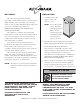
DELIVERY U N PA C K I N G This Alto-Shaam appliance has been thoroughly tested and inspected to ensure only the highest quality unit is provided. Upon receipt, check for any possible shipping damage and report it at once to the delivering carrier. See Transportation Damage and Claims section located in this manual. This appliance, complete with unattached items and accessories, may have been delivered in one or more packages.
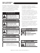
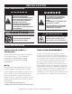
SAFETY PROCEDURES AND PRECAUTIONS Knowledge of proper procedures is essential to the safe operation of electrically and/or gas energized equipment. In accordance with generally accepted product safety labeling guidelines for potential hazards, the following signal words and symbols may be used throughout this manual. DANGER Used to indicate the presence of a hazard that WILL cause severe personal injury, death, or substantial property damage if the warning included with this symbol is ignored.
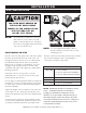
I N S TA L L AT I O N S I T E I N S TA L L AT I O N DANGER IMPROPER INSTALLATION, ALTERATION, ADJUSTMENT, SERVICE, OR MAINTENANCE COULD RESULT IN SEVERE INJURY, DEATH, OR CAUSE PROPERTY DAMAGE. READ THE INSTALLATION, OPERATING AND MAINTENANCE INSTRUCTIONS THOROUGHLY BEFORE INSTALLING OR SERVICING THIS EQUIPMENT. CAUTION TO PREVENT PERSONAL INJURY, USE CAUTION WHEN MOVING OR LEVELING THIS APPLIANCE.
I N S TA L L AT I O N S I T E I N S TA L L AT I O N ® THE OVEN MUST REMAIN ON THE PALLET WHILE BEING MOVED TO THE INSTALLATION SITE BY FORK LIFT OR PALLET LIFT TRUCK. NOTE: Note dimensions required for doorways and aisles for access of the oven and pallet to the installation site. Transport the oven in an upright and level position only. Do not tilt the oven. POSITIONING ON SITE Lift the oven from the pallet with a fork lift or pallet lift truck positioned at the front of the oven.
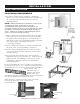
I N S TA L L AT I O N S I T E I N S TA L L AT I O N POSITIONING REQUIREMENTS ❑ In order to ensure proper ventilation, a minimum distance of at least 6-inches (152mm) must be kept from the control panels side (left) of the oven and any adjoining surfaces. NOTE: Additional clearance is needed for service access. A minimum distance of 18-inches is strongly recommended.
I N S TA L L AT I O N C O M M O N S P E C I F I C AT I O N S ■ CombiGuard™ BWS Blended Water System (INCLUDES 50 GALLON TANK, 1 MEMBRANE & 3 FILTERS) FI-28727 ■ CombiGuard™ BWS Replacement Filter Cartridge AMS-QT FI-29316 ■ CombiGuard™ BWS Replacement Filter Cartridge SCLX2-Q ■ CombiGuard™ BWS Replacement Prefilter Filter Cartridge CTO-Q CombiGuard™ Triple-Guard Water Filtration System ( INCLUDES 1 CARTRIDGE ) ■ 6•10, 7•14, 10•18 (CombiGuard™ 10) ■ 12 • 20 (CombiGuard™ 20) CombiGuard™ Triple-Guar
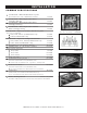
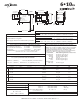
6•10ES 30" (761mm) 2" (50mm) 4-15/16" (125mm) 33-1/8" (840mm) 6-3/8" (161mm) 27-11/16" (702mm) 35-3/16" (893mm) Electrical Connection (Bottom) 7-9/16" (192mm) Steam Vent (Top) Treated Water Intake (Bottom) 60-9/16" (1538mm) 11-1/8" (282mm) 13-1/2" (342mm) 15-3/4" (400mm) Untreated Water Intake (Bottom) 34-1/16" (864mm) 31-3/8" (796mm) 43-7/8" (1114mm) 41-15/16" (1064mm) Water Drain (Back) 2-1/8" (53mm) 3-5/8" (92mm) WATER DRAIN 17-15/16" (456mm) 7-9/16" (191mm) DIMENSIONS: H x W x D
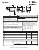
6•10ESi 30" (761mm) 2" (50mm) 4-15/16" (125mm) 33-1/8" (840mm) 6-3/8" (161mm) 27-11/16" (702mm) 35-3/16" (893mm) Electrical Connection (Bottom) 7-9/16" (192mm) Steam Vent (Top) Treated Water Intake (Bottom) 60-9/16" (1538mm) 11-1/8" (282mm) 13-1/2" (342mm) 15-3/4" (400mm) Untreated Water Intake (Bottom) 34-1/16" (864mm) 31-3/8" (796mm) 43-7/8" (1114mm) 41-15/16" (1064mm) Water Drain (Back) 2-1/8" (53mm) 3-5/8" (92mm) 7-9/16" (191mm) WATER DRAIN 17-15/16" (456mm) DIMENSIONS: H x W x D
6•10ESiN 21-7/8" (555mm) Water Drain (Side Back) 2" (50mm) 5" (126mm) 25" (635mm) 6-3/8" (161mm) Treated Water Intake (Bottom) Electrical Connection (Bottom) 35-3/16" (893mm) 26-3/4" (679mm) Steam Vent (Top) 7-9/16" (192mm) Untreated Water Intake (Bottom) 35-9/16" (903mm) 32-15/16" (835mm) 35-13/16" (909mm) 33-7/8" (859mm) 54-1/8" (1374mm) 9-9/16" (242mm) 12-5/16" (312mm) 19-1/2" (495mm) 2-1/16" (52mm) 3-5/8" (92mm) WATER DRAIN 21-11/16" (550mm) 7-1/2" (190mm) 41-1/16" (1042mm) DIMENS
10•10ES 30" (761mm) 2" (50mm) 34-1/16" (865mm) 33-1/16" (840mm) 4-15/16" (125mm) 6-1/4" (158mm) 33-15/16" (861mm) 31-3/8" (796mm) 7-9/16" (192mm) Electrical Connection (Bottom) 43-7/8" (1114mm) 41-15/16" (1064mm) 60-9/16" (1538mm) 11-1/8" (282mm) 15-3/4" (400mm) 13-1/2" (342mm) Untreated Water Intake (Bottom) Treated Water Intake (Bottom) Steam Vent (Top) Water Drain (Back) 3-5/8" (92mm) 41-1/2" (1053mm) 2-1/8" (53mm) Water Drain 17-15/16" (456mm) 7-9/16" (191mm) DIMENSIONS: H x W x D
10•10ESi 30" (761mm) 2" (50mm) 34-1/16" (865mm) 33-1/16" (840mm) 4-15/16" (125mm) 6-1/4" (158mm) 33-15/16" (861mm) 31-3/8" (796mm) 7-9/16" (192mm) Electrical Connection (Bottom) 43-7/8" (1114mm) 41-15/16" (1064mm) 60-9/16" (1538mm) 11-1/8" (282mm) 15-3/4" (400mm) 13-1/2" (342mm) Untreated Water Intake (Bottom) Treated Water Intake (Bottom) Steam Vent (Top) Water Drain (Back) 3-5/8" (92mm) 41-1/2" (1053mm) 2-1/8" (53mm) 7-9/16" (191mm) Water Drain 17-15/16" (456mm) DIMENSIONS: H x W x
10•10ESiN 21-15/16" (557mm) 35-7/8" (910mm) Water Drain (Rear) 2" (50mm) 25" (635mm) 5" (126mm) 6-3/8" (161mm) Electrical Connection(Bottom) 41-3/8" (1050mm) Treated Water Intake (Bottom) 33" (837mm) 33-7/8" (859mm) Steam Vent (Top) 7-9/16" (192mm) Untreated Water Intake (Bottom) 35-11/16" (905mm) 33-7/8" (860mm) 54-1/8" (1375mm) (242mm) 12-5/16" (312mm) 9-9/16" 19-1/2" (495mm) 2-1/16" (52mm) 3-5/8" (92mm) WATER DRAIN 21-11/16" (550mm) 7-9/16" (191mm) 41-1/16" (1043mm) DIMENSIONS:
7•14ES 13" (330mm) 15-3/4" (400mm) 22-5/8" (576mm) 2-5/16" (58mm) 3-3/4" (95mm) FRONT VIEW SIDE VIEW DIMENSIONS: H x W x D EXTERIOR : I N S TA L L AT I O N R E Q U I R E M E N T S 34-1/4" x 43-7/8" x 42-13/16" (869mm x 1114mm x 1087mm) EXTERIOR WITH RECESSED DOOR : Oven must be installed level. 34-1/4" x 47-7/8" x 42-13/16" (869mm x 1216mm x 1087mm) Hood installation is required. INTERIOR : Water supply shut-off valve and back-flow preventer.
7•14ESi 13" (330mm) 15-3/4" (400mm) 22-5/8" (576mm) 2-5/16" (58mm) 3-3/4" (95mm) FRONT VIEW SIDE VIEW DIMENSIONS: H x W x D EXTERIOR : I N S TA L L AT I O N R E Q U I R E M E N T S 34-1/4" x 43-7/8" x 42-13/16" (869mm x 1114mm x 1087mm) EXTERIOR WITH RECESSED DOOR : Oven must be installed level. 34-1/4" x 47-7/8" x 42-13/16" (869mm x 1216mm x 1087mm) Hood installation is required. INTERIOR : Water supply shut-off valve and back-flow preventer.
10•18ES 43-7/8" (1114mm) 41-15/16" (1064mm) Electrical Connection (Bottom) 33-1/8" (840mm) 6-1/4" (158mm) Treated Water Intake (Bottom) 40-7/16" (1026mm) 40-1/8" (1019mm) Steam Vents (Top) 69-3/8" (1761mm) Untreated Water Intake (Bottom) 42-13/16" (1087mm) 7-9/16" (192mm) Water Drain (Back) 12-3/4" (323mm) 15-1/2" (393mm) 22-3/8" (568mm) 4-11/16" (120mm) 2-5/16" (58mm) 32-7/8" (834mm) 30" (760mm) Water Drain (Bottom) 25-5/8" (650mm) 8-11/16" (219mm) 4-15/16" (125mm) 2" (50mm) 46-7/8" (11
10•18ESi 43-7/8" (1114mm) 41-15/16" (1064mm) Treated Water Intake (Bottom) Electrical Connection (Bottom) 33-1/8" (840mm) 6-1/4" (158mm) Steam Vents (Top) 40-7/16" (1026mm) 7-9/16" (192mm) Untreated Water Intake (Bottom) 69-3/8" (1761mm) 22-3/8" (568mm) 15-1/2" (393mm) 12-3/4" (323mm) Water Drain (Back) 42-13/16" (1087mm) 32-7/8" (834mm) 30" (760mm) 4-11/16" (120mm) 2-5/16" (58mm) 4-15/16" (125mm) 40-1/8" (1019mm) Water Drain (Bottom) 25-5/8" (650mm) 8-11/16" (219mm) 2" (50mm) 46-7/8" (119
2" (50mm) 40-15/16" (1039mm) 7-11/16" (195mm) 54-3/8" (1381mm) Treated Water Intake (Bottom) Electrical Connection (Bottom) Steam Vents (Top) 46-1/2" (1155mm) Untreated Water Intake (Bottom) 48" (1218mm) 8-15/16" (226mm) 4-1/4" (106mm) 46-3/4" (1186mm) 44-3/4" (1136mm) 11-7/8" (302mm) Water Drain (Back) 76-15/16" (1954mm) 13-1/16" (331mm) 6-11/16" (169mm) 22-11/16" (576mm) 15-13/16" (401mm) 12•20ES 45-5/16" (1151mm) Water Drain (Bottom) 33-1/2" (851mm) 2-1/16" (52mm) 1-13/16" (46mm) 51-
2" (50mm) 40-15/16" (1039mm) 1-13/16" (46mm) 51-15/16" (1319mm) 7-11/16" (195mm) 54-3/8" (1381mm) Treated Water Intake (Bottom) Electrical Connection (Bottom) Steam Vents (Top) 46-1/2" (1155mm) Untreated Water Intake (Bottom) 48" (1218mm) 8-15/16" (226mm) 4-1/4" (106mm) 46-3/4" (1186mm) 44-3/4" (1136mm) 11-7/8" (302mm) Water Drain (Back) 76-15/16" (1954mm) 6-11/16" (169mm) 13-1/16" (331mm) 22-11/16" (576mm) 15-13/16" (401mm) 12•20ESi 45-5/16" (1151mm) Water Drain (Bottom) 33-1/2" (851mm
20•20ES 51-15/16" (1319mm) 40-15/16" (1039mm) 7-11/16" (195mm) 76-1/4" (1936mm) 67-3/8" (1710mm) 2" (50mm) Steam Vents (Top) 8-15/16" (226mm) Electrical Connection (Bottom) Untreated Water Intake (Bottom) Treated Water Intake (Bottom) 48" (1218mm) 45-5/16" (1151mm) 76-15/16" (1954mm) 12-15/16" (326mm) 24-7/8" (629mm) 4-3/4" (120mm) 27-5/8" (699mm) 46-3/4" (1186mm) 44-3/4" (1136mm) 11-7/8" (302mm) Water Drain (Back) 5" (127mm) Water Drain (Bottom) 33-1/2" (851mm) 2-1/16" (52mm) 1-13/16" (
20•20ESi 51-15/16" (1319mm) 40-15/16" (1039mm) 7-11/16" (195mm) 76-1/4" (1936mm) 67-3/8" (1710mm) 2" (50mm) Steam Vents (Top) 8-15/16" (226mm) Electrical Connection (Bottom) Untreated Water Intake (Bottom) Treated Water Intake (Bottom) 48" (1218mm) 45-5/16" (1151mm) 76-15/16" (1954mm) 12-15/16" (326mm) 24-7/8" (629mm) 4-3/4" (120mm) 27-5/8" (699mm) 46-3/4" (1186mm) 44-3/4" (1136mm) 11-7/8" (302mm) Water Drain (Back) 5" (127mm) Water Drain (Bottom) 1-13/16" (46mm) 33-1/2" (851mm) 2-1/16"
I N S TA L L AT I O N ELECTRICAL CONNECTION DANGER ENSURE POWER SOURCE MATCHES VOLTAGE STAMPED ON APPLIANCE NAMEPLATE. DANGER APPLIANCES WITH NO CORD PROVIDED BY FACTORY MUST BE EQUIPPED WITH A CORD OF SUFFICIENT LENGTH TO PERMIT THE APPLIANCE TO BE MOVED FOR CLEANING. ELECTRICAL CONNECTIONS MUST BE MADE BY A QUALIFIED SERVICE TECHNICIAN IN ACCORDANCE WITH APPLICABLE ELECTRICAL CODES.
I N S TA L L AT I O N ELECTRICAL CONNECTION DANGER To avoid electrical shock, this appliance MUST be adequately grounded in accordance with local electrical codes or, in the absence of local codes, with the current edition of the National Electrical Code ANSI/NFPA No. 70. In Canada, all electrical connections are to be made in accordance with CSA C22.1, Canadian Electrical Code Part 1 or local codes.
I N S TA L L AT I O N MOBILE EQUIPMENT RESTRAINT Any appliance that is not furnished with a power supply cord but includes a set of casters must be installed with a tether. Adequate means must be provided to limit the movement of this appliance without depending on or transmitting stress to the electrical conduit.
I N S TA L L AT I O N WAT E R Q U A L I T Y R E Q U I R E M E N T USE A DRINKING QUALITY, COLD WATER SUPPLY ONLY Water quality is of critical importance when installing steam producing equipment of any kind, particularly hig h temperature steam producing equipment. Water that is perfectly safe to drink is composed of chemical characteristics that directly affect the metal surfaces of steam producing equipment. These chemical characteristics differ greatly from region to region throughout the U.S.
I N S TA L L AT I O N WAT E R C O N N E C T I O N S Flush the water line at the installation site. WAT E R R E Q U I R E M E N T S Install water intake filters (provided) [see figure 1] before connecting the oven to the water supply. TWO (2) COLD WATER INLETS - DRINKING QUALITY 3/4" NPT* ONE (1) UNTREATED WATER INLET: 3/4" NPT* LINE PRESSURE: 30 to 90 psi 2.8 to 6.
I N S TA L L AT I O N W AT E R V A LV E S H U T - O F F V A LV E S H O W N IN THE OFF POSITION NOTE: TH E SH UT-OFF VA LV E MUST BE IN TH E OPEN POSITION WH EN TH E OV EN IS BEIN G USED. WAT E R D R A I N A G E The oven must discharge through an indirect waste pipe by means of an air gap. The drain fitting is supplied with a 1-1/2-inch (41mm) NPT thread. A union is required. Install a 1-1/2-inch (41mm) diameter connection, drain line and clamp into place.
I N S TA L L AT I O N COMBITOUCH™ CHECKLIST Use this list as a final check of oven installation conformance. Damage directly attributed to improper set up, installation, or cleaning can invalidate warranty claims. ARE ALL CLEARANCE CLEARANCES: Left: 6" (152mm) — Service access of 18" (457mm) recommended. 20" (508mm) from heat producing equipment. Right: 4" (102mm) Back: 4" (102mm) for plumbing Top: 20" (508mm) for air movement REQUIREMENTS MET? Verify electrical power requirements for oven.
I N S TA L L AT I O N ERROR CODES This section is provided for the assistance of qualified technicians only and is not intended for use by untrained or unauthorized service personnel. If your Alto-Shaam® unit is not operating properly, check the following before calling your Authorized Alto-Shaam Service Agent: ☛ Check the power flow to the unit. Plug in outlet? Do not attempt to repair or service the CombiOven™ beyond this point. Contact Alto-Shaam for the nearest authorized service agent.
I N S TA L L AT I O N ERROR CODES Error Code Display Shows E20 HACCP Only - B11 Core Temperature Probe Single Point Fault When does the error occur? Possible reason Single point core temperature probe defect or disconnected — Clean Probe Receptacle Pins with sand paper. — B11 Single Point Core Temperature probe with quick connect, defective. — B11 Single Point Core Temperature probe wires with quick connect, disconnected. — B11 Single Point Core Temperature probe receptacle, defective.
I N S TA L L AT I O N ERROR CODES Error Code Display Shows When does the error occur? Possible reason E42 B5 Bypass Probe Short to Frame Bypass steam temperature probe — B5 bypass steam temperature probe defective short to ground — Probe connection problem. E43 N6 Cavity Probe Short to Frame Cavity temperature probe short to — N6 oven cavity temperature probe defective ground — Probe connection problem.
I N S TA L L AT I O N ERROR CODES When the oven malfunctions, an error code will appear in the display. PRESS THE START ICON TO ACKNOWLEDGE THE ERROR. The icons that begin to flash represent operational modes that are still usable. When the oven fault is corrected, the Combitherm will return to normal Operation.
I N S TA L L AT I O N ERROR CODES Motor Control Error Codes Type of Error Indication Release of Error Undervoltage LED flashing sequence, with 1 flash per period. Voltage of intermediate circuit is less than 250V Overvoltage LED flashing sequence, with 2 flashes per period. Voltage of intermediate circuit exceeds 445V Excess Temperature LED flashing sequence, with 3 flashes per period.
I N S TA L L AT I O N VENTLESS HOOD OPTION The Ventless Hood option is factory installed directly on the top of the Alto-Shaam Combitherm oven. The hood is designed to vent clean air back into the kitchen, filtering vapors and grease. A high-power fan draws steam and fumes into the hood intake and out the top surface exhaust vent. Fumes and vapors are circulated through filters draining the condensation through a drain at the rear of the hood.
I N S TA L L AT I O N VENTLESS HOOD OPTION TOP EXHAUST VENT O P E R AT I O N Turn the ventless hood power knob “ON”. Wait five seconds, then press the “COMBI RESET” button. Turn the Combitherm oven power “ON”. Ventless Hood Power Knob Emergency Latch Release: This release is to be used ON LY if the timed latch mechanism is not TOP LEVEL ASSY, VHES-5 HOOD FORoutage.
O R I G I N A L E Q U I P M E N T L I M I T E D WA R R A N T Y Alto-Shaam, Inc. warrants to the original purchaser that any original part that is found to be defective in material or workmanship will, at Alto-Shaam’s option, subject to provisions hereinafter stated, be replaced with a new or rebuilt part. The labor warranty remains in effect one (1) year from installation or fifteen (15) months from the shipping date, whichever occurs first.
T R A N S P O R TAT I O N D A M A G E A N D C L A I M S All Alto-Shaam equipment is sold F.O.B. shipping point, and when accepted by the carrier, such shipments become the property of the consignee. Should damage occur in shipment, it is a matter between the carrier and the consignee. In such cases, the carrier is assumed to be responsible for the safe delivery of the merchandise, unless negligence can be established on the part of the shipper. 1.