Combitherm® Combination Oven / Steamer E S GAS C O M B I TO U C H ™ SERIES 6•10 E S G 10•10 E S G 7•14 E S G 10•20 E S G 12•18 E S G 20•20 E S G • I N STALLAT I O N W164 N9221 Water Street • P.O. Box 450 • Menomonee Falls, Wisconsin 53052-0450 USA PHONE: 262.251.3800 • 800.558.8744 USA/CANADA FAX: 262.251.7067 • 800.329.8744 U.S.A. ONLY WWW.ALTO-SHAAM.COM PRINTED IN U.S.A.
Delivery........................................................................... 1 Unpacking...................................................................... 1 Safety Procedures and Precautions............................... 2 Electrical Connection................................................ 13 Mobile Equipment Restraint...................................... 14 Ventilation Requirements.......................................... 15 Gas Supply & Installation........................................
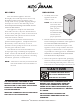
DELIVERY UNPACKING This Alto-Shaam appliance has been thoroughly tested and inspected to ensure only the highest quality unit is provided. Upon receipt, check for any possible shipping damage and report it at once to the delivering carrier. See Transportation Damage and Claims section located in this manual. This appliance, complete with unattached items and accessories, may have been delivered in one or more packages.
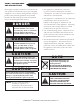
SAFETY PROCEDURES AND PRECAUTIONS Knowledge of proper procedures is essential to the safe operation of electrically and/or gas energized equipment. In accordance with generally accepted product safety labeling guidelines for potential hazards, the following signal words and symbols may be used throughout this manual. DANGER Used to indicate the presence of a hazard that WILL cause severe personal injury, death, or substantial property damage if the warning included with this symbol is ignored.
INSTALLATION SITE INSTALLATION DANGER DANGER IMPROPER INSTALLATION, ALTERATION, ADJUSTMENT, SERVICE, OR MAINTENANCE COULD RESULT IN SEVERE INJURY, DEATH, OR CAUSE PROPERTY DAMAGE. AVERTISSEMENT : UNE INSTALLATION, UN AJUSTEMENT, UNE ALTÉRATION, UN SERVICE OU UN ENTRETIEN NON CONFORME AUX NORMES PEUT CAUSER DES DOMMAGES À LA PROPRIÉTÉ, DES BLESSURES OU LA MORT. READ THE INSTALLATION, OPERATING AND MAINTENANCE INSTRUCTIONS THOROUGHLY BEFORE INSTALLING OR SERVICING THIS EQUIPMENT.
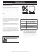
INSTALLATION SITE INSTALLATION POSITIONING ON SITE Lift the oven from the pallet with a fork lift or pallet lift truck positioned at the front of the oven. For damage protection, the use of two wooden boards, placed between the bottom of the oven and the lifting forks, is strongly recommended. To avoid damage, position the lift forks to the left of the condenser and right of the right leg as indicated in the diagram above. Stand the oven in a level position.
INSTALLATION SITE INSTALLATION POSITIONING REQUIREMENTS q In order to ensure proper ventilation, a minimum distance of at least 6-inches (152mm) must be kept from the control panels side (left) of the oven and any adjoining surfaces. NOTE: Additional clearance is needed for service access. A minimum distance of 18-inches is strongly recommended. If adequate service clearance is not provided, it will be necessary to disconnect the gas, water, and drain to move the oven with a fork lift for service access.
INSTALLATION COMMON SPECIFICATIONS q CombiGuard™ BWS Blended Water System FI-28727 (INCLUDES 50 GALLON TANK, 1 MEMBRANE & 3 FILTERS) q CombiGuard™ BWS Replacement Filter Cartridge AMS-QT FI-29316 q CombiGuard™ BWS Replacement Filter Cartridge SCLX2-Q FI-29317 q CombiGuard™ BWS Replacement Prefilter Filter Cartridge CTO-Q FI-29318 CombiGuard™ Triple-Guard Water Filtration System (INCLUDES 1 CARTRIDGE) q 6•10, 10•10, 7•14 (CombiGuard™ 10) q 10•20, 12•18, 20•20 (CombiGuard™ 20) FI-23014 FI-28728 Co
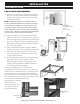
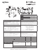
15-3/16" (385mm) Water Drain (Back Side) 40-1/8" (1018mm) 58-3/16" (1478mm) 6-1/4" (159mm) 24-1/4" (615mm) 30-1/2" (774mm) 35-1/4" (895mm) Steam Vent (Top) A B C D A = UNTREATED WATER B = TREATED WATER C = ELECTRICAL D = GAS 42-1/16" (1068mm) 2" (50mm) 25" (635mm) 21-11/16" (550mm) 5-3/16" (131mm) WATER QUALITY MINIMUM STANDARDS TWO (2) COLD WATER INLETS - DRINKING QUALITY * Can manifold off of one 3/4” line.
2" (50mm) ONE (1) TREATED WATER INLET: 3/4” NPT* ONE (1) UNTREATED WATER INLET: 3/4” NPT* 30 to 90 psi * Can manifold off of one 3/4” line. 2.8 to 6.
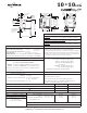
7•14 ESG 49-13/16" (1265mm) Water Drain (Side Back) Steam Vent (Top) 73-7/16" (1865mm) 2" (50mm) 31-3/4" (805mm) 33-1/8" (840mm) [D] 4-5/8" (116mm) A = UNTREATED WATER B = TREATED WATER C = ELECTRICAL D = GAS TWO (2) COLD WATER INLETS - DRINKING QUALITY 30 to 90 psi LINE PRESSURE: * Can manifold off of one 3/4” line. 2.8 to 6.
10•20 ESG 44" (1118mm) 7-7/8" (200mm) 30-5/8" (778mm) 32-13/16" (833mm) 55-7/16" (1407mm) 2-3/16" (56mm) 2" (50mm) 22-11/16" (575mm) Water Drain (Bottom) 31-3/4" (805mm) 2" (50mm) A = UNTREATED WATER B = TREATED WATER C = ELECTRICAL D = GAS 54-1/8" (1374mm) 8-15/16" (226mm) 40-5/8" (1032mm) Steam Vent (Top) [D] 4-5/8" (116mm) 12-13/16" (325mm) 47-7/8" (1215mm) 49-9/16" (1258mm) C A B D 42-7/16" (1077mm) 49-13/16" (1265mm) 73-13/16" (1875mm) 5-7/8" (148mm) 17-1/4" (438mm) 19-11/16" (5
12•18 ESG [D] 4-5/8" (116mm) 5-1/8" (130mm) Water Drain (Bottom) 31-3/4" (805mm) 2" (50mm) A = UNTREATED WATER B = TREATED WATER C = ELECTRICAL D = GAS 51-3/8" (1305mm) 6-1/4" (159mm) 40-9/16" (1030mm) Steam Vent (Top) 33-1/8" (840mm) 55-7/16" (1407mm) 22-11/16" (575mm) 12-13/16" (325mm) 47-7/8" (1215mm) 46-13/16" (1189mm) C A B D 42-7/16" (1077mm) 49-13/16" (1265mm) 73-13/16" (1875mm) 5-7/8" (148mm) 17-1/4" (438mm) 19-11/16" (500mm) 26-9/16" (675mm) 45-3/16" (1148mm) [D] 4-9/16" (116
20•20 ESG 17-1/4" (438mm) 49-13/16" (1264mm) 45-3/16" (1148mm) 47-13/16" (1214mm) 42-9/16" (1080mm) 76-5/8" (1946mm) 2" (50mm) A = UNTREATED WATER B = TREATED WATER C = ELECTRICAL D = GAS 55-7/16" (1407mm) 44" (1118mm) 2" (49mm) 7-11/16" (195mm) 8-15/16" (226mm) [D] 4-5/8" (116mm) 65-5/8" (1667mm) Steam Vents (Top) 74-9/16" (1893mm) C A B D 73-13/16" (1875mm) 19-11/16" (500mm) 26-9/16" (675mm) 5-7/8" (148mm) [D] 4-9/16" (116mm) [A,B] 4-3/8" (110mm) 19-15/16" (506mm) [C] 3-9/16" Water D
INSTALLATION ELECTRICAL MODEL VOLTAGE PHASE CIRCUIT AWG 6•10esG AND 6•10esG/SK 110-120 1 20 A 2 WIRE 7•14esG AND 7•14esG/SK 110-120 1 20 A 2 WIRE 10•10esG AND 10•10esG/SK 110-120 1 20 A 2 WIRE 10•20esG AND 10•20esG/SK 110-120 1 20 A 2 WIRE 12•18esG AND 12•18esG/SK 110-120 1 20 A 2 WIRE 20•20esG AND 20•20esG/SK 110-120 208-240 208-240 1 1 3 30 A 2 WIRE 3 WIRE 4 WIRE OTHER VOLTAGES AVAILABLE: Range 200 — 415V, 1 or 3 ph, 50 or 60 Hz An electrical wiring diagram is located b
INSTALLATION MOBILE EQUIPMENT RESTRAINT The gas Combitherm must use a connector that complies with The Standard for Connectors for Movable Gas Appliances, ANSI Z21.69 CSA 6.16 and addenda Z21.69a-1989. A quick disconnect devise must be installed to comply with The Standard for Quick Disconnect Devices for Use with Gas Fuel, ANSI Z21 CSA 6.9. Adequate means must be provided to limit the movement of this appliance.
INSTALLATION VENTILATION REQUIREMENTS DANGER Installation, air adjustment and/or service work must be in accordance with all local codes and must be performed by a certified service technician qualified to work on gas appliances. 1. A single gas Combitherm oven requires a minimum of 28 CFM make-up air for natural and propane gas. Kitchen ventilation must include a provision for an adequate flow of fresh air for gas combustion and to prevent a negative-pressure condition.
INSTALLATION GAS SUPPLY & INSTALLATION The Alto-Shaam gas Combitherm has been set to operate with either natural gas or propane as indicated on the identification name plate. Make certain the gas supply matches the nameplate information. Should conversion to the opposite fuel be desired, conversion parts must be ordered from the factory. Conversion must be completed by a qualified service person only. Always remember to reflect the conversion on the oven’s nameplate.
INSTALLATION GAS SUPPLY & INSTALLATION DANGER Installation, air adjustment and/or service work must be in accordance with all local codes and must be performed by a certified service technician qualified to work on gas appliances. Remove any tape or compound residue on all external thread connections before proceeding. Use an approved gas pipe sealant at all external threaded connections, Gas piping used on gas connections must avoid sharp bends that may restrict the flow of gas to the appliance.
INSTALLATION GAS SUPPLY & INSTALLATION The minimum size requirement for gas piping or a flexible connector is 3/4 - inch (19mm). For long runs of gas piping, the pipe diameter must conform to the tables in the National Fuel Gas Code, ANSI/NFPA Z223.1. A listed gas shut-off valve must be installed upstream of the appliance to shut off the gas supply during servicing. The shut-off valve should be accessible with the appliance in the normal installation position.
INSTALLATION GAS SUPPLY & INSTALLATION LEAK TESTING If a pressure leak test above 1/ 2 psi is to be performed on the building supply gas piping, the shut-off gas valve and oven inlet gas supply line must be disconnected from the building supply piping before conducting the pressure test. Failure to do so may result in damage to the manual gas valve, gas components in the oven, or both.
INSTALLATION WATER SUPPLY & INSTALLATION WATER QUALITY REQUIREMENTS USE A DRINKING QUALITY, COLD WATER SUPPLY ONLY Water quality is of critical importance when installing steam producing equipment of any kind, particularly high temperature steam producing equipment. Water that is perfectly safe to drink is composed of chemical characteristics that directly affect the metal surfaces of steam producing equipment. These chemical characteristics differ greatly from region to region throughout the U.S.
INSTALLATION WATER SUPPLY & INSTALLATION WATER REQUIREMENTS Flush the water line at the installation site. TWO (2) COLD WATER INLETS - DRINKING QUALITY ONE (1) TREATED WATER INLET: 3/4” NPT* Install water intake filters (provided) [see figure 1] before connecting the oven to the water supply. ONE (1) UNTREATED WATER INLET: 3/4” NPT* LINE PRESSURE: 30 to 90 psi 2.8 to 6.
INSTALLATION WATER VALVE SHUT-OFF VALVE SHOWN IN THE OFF POSITION NOTE: THE SHUT-OFF VALVE MUST BE IN THE OPEN POSITION WHEN THE OVEN IS BEING USED. WATER DRAINAGE The oven must discharge through an indirect waste pipe by means of an air gap. The drain fitting is supplied with a 1-1/2-inch (41mm) NPT thread. A union is required. Install a 1-1/2-inch (41mm) diameter connection, drain line and clamp into place.
COMBITOUCH™ CHECKLIST Use this list as a final check of oven installation conformance. Damage directly attributed to improper set up, installation, or cleaning can invalidate warranty claims. CLEARANCES: Left: 6” (152mm) RECOMMENDED SERVICE ACCESS OF 18” (457mm). 20” (508mm) FROM HEAT PRODUCING EQUIPMENT.
INSTALLATION CombiTouch ERROR CODES This section is provided for the assistance of qualified technicians only and is not intended for use by untrained or unauthorized service personnel. If your Alto-Shaam ® unit is not operating properly, check the following before calling your Authorized Alto-Shaam Service Agent: ☛ Check the power flow to the unit. Plug in outlet? Do not attempt to repair or service the CombiOven beyond this point. Contact Alto-Shaam for the nearest authorized service agent.
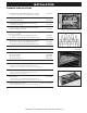
INSTALLATION CombiTouch ERROR CODES Error Code Error call out in Display Description of Error Possible reason E13 Boiler Temperature High Boiler temperature overheats — Scale build up inside steam generator. — Scale build up on water level probe. — B4 Probe connection problem. — B4 probe faulty. E15 Condensor Temperature High Excess condensor temperature — Untreated water supply line is shut off. — Untreated water supply line is connected to warm water. — B3 probe connection problem.
INSTALLATION CombiTouch ERROR CODES Error Code Error call out in Display Description of Error Possible reason E34 Steam Generator Drain Pump Fault Water level in steam generator does not drop during cleaning program — Scale build up inside the steam generator drain pump. — Scale build up inside the steam generator affecting water level probes. — Generator drain pump is faulty — Connection issue at drain pump. — No output to pump from relay board.
INSTALLATION CombiTouch ERROR CODES Error Code Error call out in Display Description of Error Possible reason E57 No rinse water During rinse no water flow is detected through solenoid valve — Water supply is shut off. — Low water pressure. — Check wiring to all components mentioned below. — Flow switch is dirty or defective. — Dual water solenoid valve obstructed or faulty (Y3.) — Relay board, high voltage, defective.
INSTALLATION CombiTouch MOTOR CONTROL ERROR CODES Type of Error Indication Release of Error Undervoltage LED flashing sequence, with 1 flash per period. Voltage of intermediate circuit is less than 250V Overvoltage LED flashing sequence, with 2 flashes per period. Voltage of intermediate circuit exceeds 445V Excess Temperature LED flashing sequence, with 3 flashes per period. Temperature sensor in the power unit is more than 93°C Overcurrent LED flashing sequence, with 4 flashes per period.
INSTALLATION ERROR CODES When the oven malfunctions, an error code will appear in the display. PRESS THE START ICON TO ACKNOWLEDGE THE ERROR. The icons that begin to flash represent operational modes that are still usable. When the oven fault is corrected, the Combitherm will return to normal operation.
ORIGINAL EQUIPMENT LIMITED WARRANTY Alto-Shaam, Inc. warrants to the original purchaser that any original part that is found to be defective in material or workmanship will, at Alto-Shaam’s option, subject to provisions hereinafter stated, be replaced with a new or rebuilt part. The labor warranty remains in effect one (1) year from installation or fifteen (15) months from the shipping date, whichever occurs first.
TRANSPORTATION DAMAGE AND CLAIMS All Alto-Shaam equipment is sold F.O.B. shipping point, and when accepted by the carrier, such shipments become the property of the consignee. Should damage occur in shipment, it is a matter between the carrier and the consignee. In such cases, the carrier is assumed to be responsible for the safe delivery of the merchandise, unless negligence can be established on the part of the shipper. 1.