Cook & Hold Oven Electronic Control Model: 300-TH/III 500-TH/III 750-TH/III 1000-TH/III 1200-TH/III 1200-TH/iii 1000-TH/iii 750-TH/iii • Installation • Operation 500-TH/iii 300-TH/iii • Maintenance W164 N9221 Water Street • p.O. Box 450 • menomonee falls, Wisconsin 53052-0450 uSa PHONE: 262.251.3800 • 800.558.8744 USA / CANADA FAX: 262.251.7067 • 800.329.8744 U . S . A . www.alto-shaam.com printed in u.s.a.
Delivery.............................................................................. 1 Unpacking.......................................................................... 1 Safety Procedures and Precautions.................................... 2 Sanitation Sanitation/Food Safety................................................ 27 Internal Food Product Temperatures........................... 27 Installation Installation Requirements.............................................. 3 Clearance Requirements....
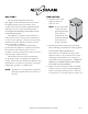
dELIVERy UNpAcKINg This Alto-Shaam appliance has been thoroughly tested and inspected to ensure only the highest quality unit is provided. Upon receipt, check for any possible shipping damage and report it at once to the delivering carrier. See Transportation Damage and Claims section located in this manual. This appliance, complete with unattached items and accessories, may have been delivered in one or more packages.
SAFETy pROcEdURES ANd pREcAUTIONS Knowledge of proper procedures is essential to the safe operation of electrically and/or gas energized equipment. In accordance with generally accepted product safety labeling guidelines for potential hazards, the following signal words and symbols may be used throughout this manual. dANgER Used to indicate the presence of a hazard that WiLL cause severe personal injury, death, or substantial property damage if the warning included with this symbol is ignored.
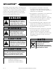
installation dANgER iMPROPER iNSTALLATiON, ALTERATiON, ADJUSTMENT, SERViCE, OR MAiNTENANCE COULD RESULT iN SEVERE iNJURY, DEATH, OR CAUSE PROPERTY DAMAGE. READ THE iNSTALLATiON, OPERATiNG AND MAiNTENANCE iNSTRUCTiONS THOROUGHLY BEFORE iNSTALLiNG OR SERViCiNG THiS EQUiPMENT. cAUTION TO PREVENT PERSONAL iNJURY, cAUTION METAL PARTS OF THiS EQUiPMENT BECOME EXTREMELY HOT WHEN iN OPERATiON. TO AVOiD BURNS, ALWAYS USE HAND PROTECTiON WHEN OPERATiNG THiS APPLiANCE.
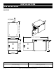
installation site I N S T A L L A T I O N 300-TH/III 25-3/16" (643mm) Cord Length: 5 ft. (1524mm) 40-5/8" (1031mm) 17-5/8" (447mm) 3/4" (19mm) 18-15/16" (480mm) 16-13/16" (426mm) 15-1/4" (387mm) 300-th3 2011 lit weight product capacity net : 69 lb (31 kg) ship : contact factory pg . 4 TH/III 36 lb (16 kg) volume maximum : installation / operation / service manual 22.
installation site I N S T A L L A T I O N 500-TH/III Cord Length 120V - 5 ft. (1524mm) 208-240V - 5 ft. (1524mm) 230V - 8 ft.
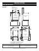
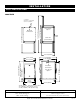
installation site I N S T A L L A T I O N 750-TH/III 34-7/8" (886mm) 54-1/8" (1373mm) Electrical Connection 79" (2006mm) Cord Length 208-240V - 5 ft. (1524mm) 230V - 8 ft. (2438mm) Pass-Through Option Electrical Connection Shown with optional bumper 28-9/16" (726mm) 34" (864mm) 26-3/4" (678mm) 31-5/8" (802mm) 17" (432mm) 25-3/4" (651mm) 33-3/8" (848mm) with 3" (76mm) casters* 5-1/8" (130mm) Elec.
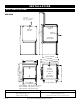
installation site I N S T A L L A T I O N 1000-TH/III 34-1/2" (876mm) 51" (1294mm) Electrical Connection 72-3/4" (1847mm) Cord Length 208-240V - 5 ft. (1524mm) 230V - 8 ft.
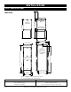
installation site I N S T A L L A T I O N 72-3/4" (1847mm) 51" (1294mm) Electrical Connection 34-1/2" (876mm) 1200-TH/III Pass-Through Option Shown with optional bumper 25-1/16" (636mm) Electrical Connection 72-1/4" (1835mm) Pass-Through Option 6-13/16" (172mm) 75-5/8" (1920mm) with 5 (127mm) casters* 22-1/2" (572mm) 34" (864mm) 31-5/8" (802mm) 17" (432mm) 20-1/2" (521mm) 24-1/4" (613mm) 23-1/2" (597mm) *73-7/8" (1877mm) - with optional 3-1/2" casters *74-11/16" (1897mm) - with optional 6
installation OPTIONS AND ACCESSORIES Bumper, Full Perimeter ( not 2-1/2" available with 300-TH/III 500-TH/III — 5011161 5010371 5009767 5009767 prime rib HL-2635 HL-2635 4459 HL-2635 4459 HL-2635 4459 HL-2635 4459 5" (127mm) 3-1/2" (89mm) 3" (76mm) 2-1/2" (64mm) — — 5015323 — casters ) Carving Holder steamship ( cafeteria ) round Casters - 2 rigid , 2 swivel w / brake Door Lock with Key Drip Pan with drain without drain extra deep HACCP Data Logger ( factory installed ) Legs, 6"
installation STAcKINg INSTRUcTIONS 1) If the two appliances were shipped together from the factory, the top unit will have the casters already removed. A stacking kit will be included with the shipment. If casters need to be removed: lay the unit on its back, and remove the set screw on each caster. Pull the casters out of the unit. 2) while appliance is laid on its back, insert one stacking post in each of the four corners of the upper unit.
installation site I N S T A L L A T I O N A number of adjustments are associated with initial installation and start-up. It is important that these adjustments be conducted by a qualified service technician. Installation and start-up adjustments are the responsibility of the dealer or user. These adjustments include but are not limited to thermostat calibration, door adjustment, leveling, electrical hook-up and installation of optional casters or legs.
installation site I N S T A L L A T I O N drip tray installation instructions - 500, 750, 1000, 1200 b d a c Item 1 Description 1 2 Drip Tray Holder 1 3 8-32 x 1/4” Phil Screw 3 4 Drip Tray 1 1. Poke holes through double-sided tape a which is attached to the back of drip tray holder b. 2. Remove backing on double-sided tape a. 3. Put screws c through holes and attach drip tray holder b to unit. 4.
installation ELECTRICAL CONNECTION The appliance must be installed by a qualified service technician. The oven must be properly grounded in accordance with the National Electrical Code and applicable local codes. Plug the unit into a properly grounded receptacle ONLY, positioning the unit so that the plug is easily accessible in case of an emergency. Arcing will occur when connecting or disconnecting the unit unless all controls are in the “off” position.
installation ELECTRICAL 3 0 0 -T H / III voltage phase cycle / hz amps kW 120 1 60 6.7 .80 nema 5-15 p 15A-125 v plug 230 1 50/60 2.7 .62 cee 7/7 220-230 v plug voltage phase cycle / hz amps kW 120 1 60 16.0 1.9 208 240 1 1 60 60 11.2 12.5 2.7 3.0 230 1 50/60 12.0 2.8 voltage phase cycle / hz amps kW 208 240 1 1 60 60 14.0 16.0 2.9 3.9 230 1 50/60 12.2 2.
o p eration USER SAFETY INFORMATION cAUTION METAL PARTS OF THiS EQUiPMENT BECOME EXTREMELY HOT WHEN iN OPERATiON. TO AVOiD BURNS, ALWAYS USE HAND PROTECTiON WHEN OPERATiNG THiS APPLiANCE. The Alto-Shaam cook and hold oven is intended for use in commercial establishments by qualified operating personnel where all operators are familiar with the purpose, limitations, and associated hazards of this appliance. Operating instructions and warnings must be read and understood by all operators and users.
o p eration Power ON Indicator gf h i j k b c d e l m upper a n lower a p o control features 1. On/Off Key The on/off control system key operates the functions of the control panel. If there is any power loss during operation, the on/off indicator light will flash. To clear, push key and release. 2. Cook Key — Temperature range 2 00° to 325°F (93° to 162°C) Used to select cooking mode and to review the cook temperature setting. 3.
o p eration O P E R A T I N G FEAT U RES & F unc tions To stop an operation at any time : Power Fail Detect: Press and hold the S tart Key until the control beeps for two seconds, indicating the operation has been cancelled. The oven will remain in a power-on state. If the power were to fail for any reason while heating, the control will retain, in memory, the programmed operating conditions.
o p eration O P E R A T I N G F EAT U RES & F unc tions Display High/Low Probe Temperatures: To observe the recorded maximum or minimum probe temperature when cooking by probe, press the following keys while the probe remains in the product: Highest Temperature: Press P robe Key and U p A rrow Key at same time. Lowest Temperature: Press P robe Key and D own A rrow Key at same time.
o p eration Cook/Hold Instructions Press and release control o n/o ff key. The oven will beep for one second and power to the unit will be indicated by an illuminated green indicator light located in the upper left corner of the o n /o ff key. The oven will begin operating in the hold mode. The amber h old indicator will be illuminated and the last set hold temperature will be displayed. To set Cook temperature — Press Cook Key.
o p eration Programming a Preset Select the product to be programmed and begin programming with the oven control power o ff . Press and release control o n/o ff key. The oven will beep for one second and power to the unit will be indicated by an illuminated green indicator light located in the upper left corner of the o n /o ff key. The oven will begin operating in the hold mode. The amber h old indicator will be illuminated and the last set hold temperature will be displayed.
O P E R A T ion user o p tions Lock Indicator Preset Lock P reset Keys Lock and Unlock Control Panel Lock and Unlock P reset Keys A through H can be locked in order to prevent storing, altering or erasing a program. The control panel can be locked at any time in order to prevent inadvertent or accidental setting changes. To lock the p reset keys, press and hold the “I” Key until the oven beeps. Release the “I” key. The green indicator on the “I” key will illuminate.
O P E R A T ion H A CCP HACCP Documentation, Data Logger - Optional This oven meets the requirements of established HACCP criteria by providing automated sampling, record keeping, set-point validation, recipe used, dates and time. This data is retained for the last 30 days. This information can be viewed on screen or downloaded to a USB drive and then copied to your computer. The file format is a comma-separated variable (*.csv), that is easily opened using a spreadsheet package.
OPERATIoN General Holding Guidelines Chefs, cooks and other specialized food service personnel employ varied methods of cooking. Proper holding temperatures for a specific food product must be based on the moisture content of the product, product density, volume, and proper serving temperatures. Safe holding temperatures must also be correlated with palatability in determining the length of holding time for a specific product.
AER EA Tan c L E A N I N g A N d p RC EV NT IVEd M Ac I Nleanin TENANcE g pROTEcTINg STAINLESS STEEL SURFAcES It is important to guard against corrosion in the care of stainless steel surfaces. Harsh, corrosive, or inappropriate chemicals can completely destroy the protective surface layer cLEANINg AgENTS Use non-abrasive cleaning products designed for use on stainless steel surfaces. Cleaning agents must be chloride-free compounds and must not contain quaternary salts.
c are an d c leanin g EQUIPMENT CARE Under normal circumstances, this oven should provide you with long and trouble free service. There is no preventative maintenance required, however, the following Equipment Care Guide will maximize the potential life and trouble free operation of this oven. The cleanliness and appearance of this equipment will contribute considerably to operating efficiency and savory, appetizing food. Good equipment that is kept clean works better and lasts longer. CLEAN DAILY 1.
c are an d c leanin g CLEAN THE DOOR VENTS DAILY PRONG CLEANING Door vents need to be inspected and cleaned as required. To ensure accurate internal product temperature readings the prongs on the removable probe must be cleaned daily. Clean the Probes Daily Remove all food soil from probes. Wipe entire probe and cable assembly with warm detergent solution and a clean cloth. Remove detergent by wiping each probe and cable with clean rinse water and a cloth.
sanitation Food flavor and aroma are usually so closely related that it is difficult, if not impossible, to separate them. There is also an important, inseparable relationship between cleanliness and food flavor. Cleanliness, top operating efficiency, and appearance of equipment contribute considerably to savory, appetizing foods. Good equipment that is kept clean, works better and lasts longer. Most food imparts its own particular aroma and many foods also absorb existing odors.
S ervi c e troubles h ooting code description possible cause E-30 Cavity air sensor reading < 5°F. Verify sensor integrity. See sensor test instructions below. Cavity air sensor reading > 517°F. Verify sensor integrity. cavity air sensor open See sensor test instructions below. product probe is shorted Product probe reading < 5°F. Verify sensor integrity. Oven will cook in time only See sensor test instructions below. product probe is open Product Probe reading > 517°F. Verify sensor integrity.
S ervi c e This section is provided for the assistance of qualified technicians only and is not intended for use by untrained or unauthorized service personnel. If your Alto-Shaam® unit is not operating properly, check the following before calling your Authorized Alto-Shaam Service Agent: ☛ Check main power circuit breaker to the unit and verify that the circuit breaker on the back of the unit is turned on, if applicable. Do not attempt to repair or service the unit beyond this point.
SERVICE EXTERIOR VIEW - 300-TH/III A 1 2 3 5 4 7 6 8 9 29 10 28 11 27 25 26 12 14 18 13 15 23 16 24 17 18 19 21 22 20 P art nu mbe rs a nd dr awings ar e s ubjec t t o c hang e w i t h o u t n o t i c e . pg .
S ervi c e E xterior servic e vie w - 3 0 0 - T H/I I I ITEM DESCRIPTION A PART No.
S ervi c e E xterior servic e vie w - 5 0 0 , 7 5 0 , 1 0 0 0 - T H/I I I 500-TH/III Shown 38 1 2 B 4 3 37 6 5 7 36 8 35 9 10 34 33 11 12 32 30 27 25 28 31 29 26 13 14 15 22 16 24 19 17 23 22 21 20 18 P art n umb ers an d d rawings ar e s ubjec t t o c hange w i t h o u t n o t i c e . dANgER dIScONNEcT UNIT FROM pOwER SOURcE BEFORE cLEANINg OR SERVIcINg. pg . 32 TH/III dANgER L O cK- O UT O R pOST BREAKER pANEL UNTI L S ERV IcE wO RK hA S BEEN cO MpL ET Ed.
S ervi c e E xterior servic e vie w - sin gle c ompartment IT EM 1 2 3 4 5 6 7 8 9 10 11 12 13 14 15 16 17 18 19 20 21 22 23 24 25 26 27 28 29 30 31 32 33 34 35 36 37 38 39* 40* 41* 42* 43* 44* 45* 46* 47* mod el > D ESC R I P T I O N THERMOSTAT, hi limit GASKET ADHESIVE 0.125 X 0.375 [lin ft] PLUG, DOME,.187" HOLE high limit protection cover rear trim, spot screw, m4-0.7 x 6mm phil bushing, strain relief cordset, 120V, 5ft. (1524mm) cordset, 208-240V, 5ft. (1524mm) cordset, 230V, 8ft.
S ervi c e E xterior servic e vie w - double c ompartment 1200-TH/III 32 C 1 30 33 2 31 3 4 34 5 6 35 A 7 29 28 8 27 A 26 9 25 10 24 23 22 21 18 11 20 15 14 19 18 17 16 13 P art numbe rs a nd dra wings ar e s ubjec t t o c hange w i t h o u t n o t i c e . pg .
S ervi c e E xterior servic e vie w - 1 2 0 0 - T H/I I I C ITE M 1 des cri ption P AR T N o . Q T Y top cover 1011534 1 ITEM 24 d es c rip tion switch, reed P A RT No. QTY sw-33559 2 2 screw, 10-32 x 1/2, nf phil, flat sc-23670 4 25 bushing, 3/8" black hole bu-3419 1 3 nut, 10-32 unf hex ms, 18-8 sst nu-2215 4 26 SHELF, stainless steel sh-2325 6 4 bracket, tether bt-26884 1 27 SIDE RACK, CHROME sr-2266 4 5 GASKET ADHESIVE 0.125 X 0.
S ervi c e E LE C TR ONI C C O MP O N E N TS - 3 0 0 - T H/I I I 230V Shown 3 2 4 1 18 5 19 20 17 6 7 16 15 8 14 13 9 12 11 10 ITE M P a r t n u m b e r s a n d d r a w i n g s a r e s u b j e c t t o c h a n g e w i th o u t n o ti ce . DES C R I P T I O N P AR T N o .
S ervi c e E LE C TR ONI C C O MP O N E N TS - 5 0 0 , 7 5 0 , 1 0 0 0 , 1 2 0 0 - T H/III 230V Shown 18 13 17 19 5 1 2 4 13 16 3 6 7 15 14 13 12 11 10 8 9 ITE M P a r t n u m b e r s a n d d r a w i n g s a r e s u b j e c t t o c h a n g e w i th o u t n o ti ce . P A RT No. QTY 1 STAR LOCK WASHER DES C R I P T I O N P AR T N o .
S ervi c e Cable Heating K its cable heating kit > ( one k i t r equi r ed p er c av i t y) item D ESC R I P T I O N #4881 #4880 (500) (750, 1000, 1200) uk only (1200) 4900W qty qty qt y 134 ft. 210 ft. 134 ft. 4 12 4 cb-3045 cable heating element cr-3226 ring connector in-3488 insulation corner 1 ft. 1 ft. 1 ft.
TH/III installation / operation / service manual pg .
pg .
TH/III installation / operation / service manual pg .
pg .
TH/III installation / operation / service manual pg .
pg .
TH/III installation / operation / service manual pg .
pg .
transPortatIon DaMaGe and claIMs 1. 2. 3. 4. 5. 6. 7. 8. All Alto-Shaam equipment is sold F.O.B. shipping point, and when accepted by the carrier, such shipments become the property of the consignee. Should damage occur in shipment, it is a matter between the carrier and the consignee. In such cases, the carrier is assumed to be responsible for the safe delivery of the merchandise, unless negligence can be established on the part of the shipper.