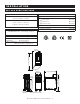
® GAS F RY E R F r y Te c h S e r i e s ASF-60G shown with basic control and optional automatic basket lifts AS F-60G and AS F-75G Gas Fryers • I N STALLATION ASF-75G shown with basic control and optional automatic basket lifts • OPERATION • MAI NTENANCE W164 N9221 Water Street • P.O. Box 450 • Menomonee Falls, Wisconsin 53052-0450 USA PHONE: 262.251.3800 • 800.558.8744 USA / CANADA FAX: 262.251.7067 • 800.329.8744 U . S . A . www.alto-shaam.com PRINTED IN U.S.A.
® DELIVERY U N PA C K I N G This Alto-Shaam appliance has been thoroughly tested and inspected to insure only the highest quality unit is provided. Upon receipt, check for any possible shipping damage and report it at once to the delivering carrier. See Transportation Damage and Claims section located in this manual. This appliance, complete with unattached items and accessories, may have been delivered in one or more packages.
I N S TA L L AT I O N SAFETY PROCEDURES AND PRECAUTIONS Knowledge of proper procedures is essential to the safe operation of electrically and/or gas energized equipment. In accordance with generally accepted product safety labeling guidelines for potential hazards, the following signal words and symbols may be used throughout this manual.
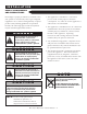
I N S TA L L AT I O N A S F - 7 5 G S P E C I F I C AT I O N S EXTERIOR H x W x D: 45-5/16" x 24-13/16" x 37-7/8" (1150mm x 630mm x 961mm) BASKET DIMENSIONS ( H X W X D) 11-1/2" x 12-3/4" x 21-3/4" (292mm x 324mm x 552mm) C A PA C I T Y SHORTENING/OIL: 73 lb (33 kg) LOAD CAPACITY: 13 lb (6 kg) WEIGHT MAXIMUM MAXIMUM EST.
I N S TA L L AT I O N A S F - 6 0 G S P E C I F I C AT I O N S DIMENSIONS EXTERIOR H x W x D: STANDARD ACCESSORIES ■ Basket, Half-Size (2 45-1/8" x 15-3/4" x 33-5/8" Brush Set ( ONE 3- BRUSH ■ ANGLE BRUSH ■ SCRUB BRUSH ■ STRAIGHT BRUSH (1146mm x 400mm x 854mm) BASKET DIMENSIONS (H X W X D) 5-7/8" x 5-3/16" x 13-13/16" (149mm x 131mm x 351mm) SET INCLUDED AS STANDARD ) OPTIONS ■ Fry Pot Cover NET WEIGHT: WEIGHT SHIP WEIGHT: EST 23-1/4" (590mm) 15 0° 47-1/2" (1206mm) 33-5/8" (854mm) 2-7
I N S TA L L AT I O N DANGER DANGER IMPROPER INSTALLATION, ALTERATION, ADJUSTMENT, SERVICE, OR MAINTENANCE COULD RESULT IN SEVERE INJURY, DEATH OR CAUSE PROPERTY DAMAGE. READ THE INSTALLATION, OPERATING AND MAINTENANCE INSTRUCTIONS THOROUGHLY BEFORE INSTALLING OR SERVICING THIS EQUIPMENT. AVERTISSEMENT : UNE INSTALLATION, UN AJUSTEMENT, UNE ALTÉRATION, UN SERVICE OU UN ENTRETIEN NON CONFORME AUX NORMES PEUT CAUSER DES DOMMAGES À LA PROPRIÉTÉ, DES BLESSURES OU LA MORT.
I N S TA L L AT I O N S I T E I N S TA L L AT I O N 1. 2. 3. 4. 5. 6. 7. 8. 9. It is the responsibility of the installer to verify that this fryer installation is in compliance with the specifications listed in this manual and with local code requirements. Hood installation is required. 10. Both cooking and cleaning functions require unobstructed access. The frypot, control panel, and front access door must be maintained free from obstruction.
I N S TA L L AT I O N V E N T I L AT I O N DANGER Installation, air adjustment and/or service work must be in accordance with all local codes and must be performed by a certified service technician qualified to work on gas appliances. An adequate ventilation system is required for commercial cooking equipment. Information may be obtained by writing to the National Fire Protection Association, Batterymarch Park, Quincy, MA 02269. When writing refer to NFPA No. 96. 1.
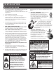
I N S TA L L AT I O N G A S S P E C I F I C AT I O N S The Alto-Shaam open gas fryer has been set to operate with either natural gas or propane as indicated on the fryer identification name plate. CONNECTING TO THE WRONG GAS SUPPLY COULD RESULT IN FIRE OR AN EXPLOSION CAUSING SEVERE INJURY AND PROPERTY DAMAGE. WA R N I N G TO AVOID SERIOUS PERSONAL INJURY, installation of this appliance must conform to local, state, and national codes; the current edition of the American National Standard Z223.
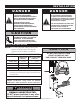
I N S TA L L AT I O N GAS CONNECTION DANGER Installation, air adjustment and/or service work must be in accordance with all local codes and must be performed by a certified service technician qualified to work on gas appliances. Use an approved gas CORRECT INCORRECT pipe sealant at all external threaded connections, gas piping used on gas connections must avoid sharp bends that may restrict the flow of gas to the appliance. If the connected pressure exceeds 14.0" W.C. (3.
I N S TA L L AT I O N RESTRAINT REQUIREMENTS - MOBILE EQUIPMENT The fryer must be supplied with a connector that complies with all state and local installation codes. Any appliance that is not furnished with a power supply cord but that includes a set of casters must be tethered. Adequate means must be provided to limit the movement of this appliance without depending on or transmitting stress to the electrical conduit. The following requirements apply: 1.
I N S TA L L AT I O N ELECTRICAL REQUIREMENTS DANGER To avoid electrical shock, this appliance MUST be adequately grounded in accordance with local electrical codes or, in the absence of local codes, with the current edition of the National Electrical Code ANSI/NFPA No. 70. In Canada, all electrical connections are to be made in according with CSA C22.1, Canadian Electrical Code Part 1 or local codes. An electrical wiring diagram is located in the front access door of the fryer.
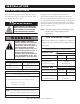
O P E R AT I O N OIL/SHORTENING REQUIREMENTS OIL/SHORTENING REQUIREMENTS The ASF-75G requires 73-pounds (33 kg) of oil or shortening in the frypot and the ASF-60G requires 62-pounds (28 kg) of oil or shortening. Use only quality, high-grade oil/shortening in the fryer. The high moisture content of many lower grade shortening will result in excessive foaming and boil over. The cold oil/shortening level requirement for the fryer is indicated below. COLD OIL or SHORTENING EXPANDS AS THE TEMPERATURE INCREASES.
O P E R AT I O N B A S I C C O N T R O L S TA R T U P & G E N E R A L O P E R AT I O N NOTE: Because each fryer station is controlled DANGER BEFORE STARTING THE APPLIANCE, MAKE CERTAIN YOU DO NOT DETECT THE ODOR OF GAS. IF THE ODOR OF GAS IS DETECTED: • DO NOT attempt to light any appliance. • DO NOT touch any electrical switches. • Extinguish any open flame. • Use a telephone OUTSIDE THE PROPERTY & IMMEDIATELY contact your gas supplier.
O P E R AT I O N D E L U X E C O N T R O L S TA R T U P & G E N E R A L O P E R AT I O N NOTE: Perform an initial Boil-Out to clean and sanitize the fryer before operating. (See page 16.) 1. Service is to be performed by an authorized Alto-Shaam service agent. 2. Assure all local electrical codes, fire codes, and all other requirements such as hood installation have been met in the process of installation. 3. Open front access door and insure drain valve is in the “ C L O S E D ” position.
O P E R AT I O N BASIC CONTROL BOIL-OUT NOTE: Perform an initial Boil-Out to clean and sanitize the fryer station before operating. Carbonized deposits along with an accumulation of oil will eventually build-up on the interior of the frypot as well as fryer accessories. It is important to periodically remove these deposits, not only to maintain fryer efficiency, but also to provide the highest product quality.
O P E R AT I O N DELUXE CONTROL BOIL-OUT NOTE: Perform an initial Boil-Out to clean and sanitize the fryer before operating.. Carbonized deposits along with an accumulation of oil will eventually build-up on the interior of the frypot as well as fryer accessories. It is important to periodically remove these deposits, not only to maintain fryer efficiency but also to provide the highest product quality. 2.
O P E R AT I O N DELUXE CONTROL BOIL-OUT 5. Press and hold the Program Key for 10 seconds. “ B o i l ” will always appear as the first item in the display whenever the “ P R O G R A M ” key is initiall y pressed. Boil Press the Right arrow key to enter the “Boil” program. The display will indicate “READY ?”. Press the Right arrow key to start the boil-out function. The boil-out solution will begin to heat to a temperature of 195°F (91°C).
O P E R AT I O N CLEANING & MAINTENANCE DANGER DISCONNECT UNIT FROM POWER SOURCE BEFORE CLEANING OR SERVICING. THOROUGHLY CLEAN DAILY The cleanliness and appearance of this unit will contribute considerably to operating efficiency and savory, appetizing food. Good equipment kept clean works better and lasts longer. 1. Disconnect unit from power source, and let cool. 2. Remove all detachable items. Clean these items separately with a good grease solvent or commercial detergent. Rinse well and dry. 3.
O P E R AT I O N A S F - 7 5 G O I L / S H O R T E N I N G F I LT R A T I O N Careful observation of the finished food product will help determine optimal filtering frequency. Filtering the cooking oil at regular intervals will help ensure food quality. F O R B E S T R E S U LT S : Do not allow the temperature of the oil to decrease below the “Idle Mode” temperature of 250°F (121°C) when filtering. Operators must be made aware of the hazards involved in the operation of a hot oil filtering system.
O P E R AT I O N A S F - 7 5 G O I L / S H O R T E N I N G F I LT R A T I O N FILTER REPLACEMENT 1. With the DRAIN in the “CLOSED” position, pull the trolley from the fryer and disconnect the hose from the fryer. 2. Pushing down on filter frame clip, pull side of filter cartridge closest to clip upwards. Slide opposite edge of filter cartridge out from beneath the filter frame lip. 3. Remove and discard used filter A FILTER CARTRIDGE . 4.
O P E R AT I O N A S F - 7 5 G O I L / S H O R T E N I N G F I LT R A T I O N FILTER CLEANING & MAINTENANCE NOTE: Make certain to use hand protection when working with hot surfaces. R E U S A B L E M E S H F I LT E R O P T I O N : Clean the reusable mesh filter (FI-27014) by spraying thoroughly with hot water. DO NOT clean in the dishwasher. DO NOT use detergents to clean. Detergents and detergent residues will significantly reduce the life of oil and shortening products.
O P E R AT I O N A S F - 7 5 G O I L / S H O R T E N I N G F I LT R A T I O N CLEANING & MAINTENANCE OIL DISCARD HOSE OPTION: The oil discard hose option (HO-27686) is available as an option to assist both the boil-out and filtration operation. With the discard hose attached to the nozzle connection, place the Kettle/Nozzle selector in the “NOZZLE ON” position. NOZZLE POSITION The drain can be placed in the “OPEN” or “CLOSED” position as required.
O P E R AT I O N ALL SUGGESTED FRYING TIMES ARE BASED ON A FULL LOAD OF PRODUCT Remove ice crystals and ensure that food is dry before frying. Excessive water and ice can cause oil to splatter or overflow. Do not over fill the basket. Food needs to be surrounded by oil for best frying results. S UGGES TED FRYING TIMES PROGRAM KEYS ITEM MINUTES T E M P E R AT U R E D I S P L AY 1. Fries ( FROZEN ) 3:30 350°F (177°C) Fries 2. Chicken Nuggets ( FROZEN ) 3:30 350°F (177°C) Nuggets 3.
O P E R AT I O N ALL SUGGESTED FRYING TIMES ARE BASED ON A FULL LOAD OF PRODUCT Remove ice crystals and ensure that food is dry before frying. Excessive water and ice can cause oil to splatter or overflow. Do not over fill the basket. Food needs to be surrounded by oil for best frying results.
B A S I C C O N T R O L O P E R AT I O N PA N E L I D E N T I F I C AT I O N C O N T R O L PA N E L I D E N T I F I C AT I O N 1. L.E.D. 4-DIGIT DISPLAY 6. RIGHT BASKET BUTTON 2. LEFT BASKET BUTTON 7. RIGHT BASKET INDICATOR LIGHT 3. LEFT BASKET INDICATOR LIGHT 8. BOIL OUT BUTTON 4. TEMP DISPLAY BUTTON 9. PROGRAM BUTTON 5. SYNC BASKET BUTTON (Optional) CAUTION METAL PARTS OF THIS EQUIPMENT BECOME EXTREMELY HOT WHEN IN OPERATION.
B A S I C C O N T R O L O P E R AT I O N L E F T A N D R I G H T B A S K E T O P E R AT I O N NOTE: Because each fryer station is controlled separately, the following procedures must be followed for every component fryer in multiple-station units. 1. Ensure that the fryer has reached the set-point temperature and it is displayed on the control panel. ( FOLLOW INSTRUCTIONS ON THE START UP AND GENERAL OPERATION PAGE ) 350 F 2.
B A S I C C O N T R O L O P E R AT I O N L E F T A N D R I G H T B A S K E T O P E R AT I O N 6. Press the L E F T B A S K E T or R I G H T B A S K E T button to stop alarm. 7. R E M O V E P R O D U C T NOTE: To stop the cooking function of either basket before the programmed time, press the L E F T B A S K E T or R I G H T B A S K E T button. 03:00 The Indicator Light for that basket will go out. The display will revert to the other basket’s remaining time or the frypot temperature.
B A S I C C O N T R O L O P E R AT I O N SYNCHRONIZED BASKETS OPTION NOTE: Because each fryer station is controlled separately, the following procedures must be followed for every component fryer in multiple-station units. 1. Ensure that the fryer has reached the set-point temperature and it is displayed on the control panel. ( FOLLOW INSTRUCTIONS ON THE START UP AND GENERAL OPERATION PAGE ) 350 F 2. L O A D P R O D U C T Load product in baskets and set baskets in the fryer lift brackets. 3.
B A S I C C O N T R O L O P E R AT I O N CONTROL PROGRAMMING OVERVIEW This section is provided for the assistance of qualified personnel only and is not intended for use by untrained or unauthorized personnel. NOTE: Because each fryer station is controlled separately, the following procedures must be followed for every component fryer in multiple-station units.
B A S I C C O N T R O L O P E R AT I O N PROGRAMMING THE CONTROL This section is provided for the assistance of qualified personnel only and is not intended for use by untrained or unauthorized personnel. NOTE: Because each fryer station is controlled separately, the following procedures must be followed for every component fryer in multiple-station units. 1. Enter Control Programming. Press the P R O G R A M button. • • If unlocked, the display will go right into the Control Programming sequence.
B A S I C C O N T R O L O P E R AT I O N PROGRAMMING THE CONTROL This section is provided for the assistance of qualified personnel only and is not intended for use by untrained or unauthorized personnel. 5. Choose the correct melt cycle for your frying compound. The melt cycle will appear in the L E D as “ C Y L ” or “ C Y S ” . “ C Y L ” is for liquid frying compounds such as oil and “ C Y S ” is for solid frying compounds such as shortening. Do not choose “ C Y 0 ” .
BASIC CONTROL TROUBLESHOOTING T E M P E R AT U R E V E R I F I C AT I O N NOTE: Because each fryer station is controlled separately, the following procedures must be followed for every component fryer in multiple-station units. The temperature of the cooking oil / shortening and the temperature set-point can be verified at any time. Press T E M P D I S P L AY button once to verify the actual temperature of the cooking oil / shortening.
D E L U X E C O N T R O L O P E R AT I O N PA N E L I D E N T I F I C AT I O N 21 27 28 24 22 26 25 D U A L C O N T R O L PA N E L I D E N T I F I C AT I O N 1. POWER ON KEY 15. — 2. POWER ON INDICATOR LIGHT 16. L.E.D. 4-DIGIT DISPLAY 3. L.E.D. 4-DIGIT DISPLAY 17. ALPHA/NUMERIC DISPLAY 4. ALPHA/NUMERIC DISPLAY 18. PROGRAMMED PRODUCT KEYS (6) 5. PROGRAMMED PRODUCT KEYS (6) 19. PROGRAMMED PRODUCT WINDOWS (6) 6.
D E L U X E C O N T R O L O P E R AT I O N P R O G R A M M E D P R O D U C T K E Y O P E R AT I O N 1 . TURN THE POWER SWITCH LOCATED BEHIND THE LOWER FRONT ACCESS DOOR TO THE “ON” POSITION. Press the H I - L I M I T R E S E T button. ➧ The HI-LIMIT ALARM light will go out. ➧ Both LED displays on the control panel will indicate OFF. 2. Press and hold the ON/OFF key for 1-1/2 to 2 seconds to energize the fryer.
D E L U X E C O N T R O L O P E R AT I O N P R O G R A M M E D P R O D U C T K E Y O P E R AT I O N 5 . If shake-time has been programmed into the selected product: “SHAKE” 0:10 ˚ Shake An alarm will sound during the cooking cycle at the specified shake-time programmed. “SHAKE” will appear in the display. The basket will automatically lift 50- percent and the display will count down from the shake time programmed.
D E L U X E C O N T R O L O P E R AT I O N M A N U A L O P E R AT I O N 1. Press and hold the ON/OFF key for 1 second to energize the fryer. ➪ The following will appear in the Alpha/Numeric Display: “MELTCYC” 75 °F Melt-Cyc The fryer will start the melt-cycle mode. This is the required mode for melting solid shortening within the frypot. The fryer will generate ON/OFF heating cycles and will remain in this mode until 180°F (82°C) is reached or the mode is manually bypassed.
D E L U X E C O N T R O L O P E R AT I O N M A N U A L O P E R AT I O N 5. Press the MANUAL TIME key after the correct amount of time has been entered. 3:30 Manual The fryer basket will automatically lower into the cooking shortening/oil. The displayed time will begin to count down the remaining time. N O T E : To stop the manual cooking function before time has expired: Press and hold the MANUAL TIME key for 1-second. ➪ The display will revert to “0:00.” The control will produce an audible signal.
D E L U X E C O N T R O L O P E R AT I O N CONTROL PROGRAMMING OVERVIEW Initial access to the programming mode must start with the control in the OFF position. OFF Entering the “PROGRAM” mode provides the operator with the ability to modify all control functions and provides access to the boil-out “BOIL” feature. The fryer programming capability offers the following functions and features.
D E L U X E C O N T R O L O P E R AT I O N PROGRAMMING THE CONTROL Starting with the control in the OFF position, press and hold the “PROGRAM” key for a period of 5 to 10 seconds. “Boil” will always appear as the first item in the display whenever the “PROGRAM” key is initially pressed. Detailed boil-out instructions are located on Press the DOWN “Boil” Boil 12 of this manual. arrow key to bypass the “Boil” program. PAGE Press the right arrow key enter the “Boil” program ( SEE PAGE 12).
D E L U X E C O N T R O L O P E R AT I O N PROGRAMMING THE CONTROL “SetPoint 3 5 0 °F SetPoint This program allows the operator to change the temperature of the frypot oil/shortening. The set-point temperature of the oil/shortening can be adjusted from a range of 250°F to 450°F (121°C to 232°C). The factory default is set at 350°F (177°C). Press the Up or Down arrow keys to scroll until “SetPoint” appears in the display. Press the right arrow key to enter the program. Display stops flashing.
D E L U X E C O N T R O L O P E R AT I O N PROGRAMMING THE CONTROL “Product” Product The fryer control has been preset at the factory with four product menu items and two programmable spaces in the dual control. 1. Fries 2. Nuggets 3. Fish 4. Chicken 5. PRODUCT A 6. PRODUCT B The number of available product keys is directly linked to the “LiftSync” program that provides the ability to raise both baskets simultaneously or independently.
D E L U X E C O N T R O L O P E R AT I O N PROGRAMMING THE CONTROL “Product” Product “Item” Press and hold any one of the twelve product keys to be programmed or modified. The product, as currently named, will begin to flash in the display. arrow key. The first letter of the product name will begin to flash.
D E L U X E C O N T R O L O P E R AT I O N PROGRAMMING THE CONTROL “Product” Product “TimeMod” OFF TimeMod This sub-menu allows the operator to compensate for any drop in oil/shortening temperature as it relates to cooking start time. In the “ON” position, the product countdown timer will not start until the oil temperature reaches the set-point temperature. In the “OFF” position, the product countdown timer will start as soon as the product key is pressed. This item is set to “OFF” at the factory.
D E L U X E C O N T R O L O P E R AT I O N PROGRAMMING THE CONTROL “Product” Product “ShakTime” OFF ShakTime The “ShakTime” sub-menu provides the operator with a programmed time period during which the baskets will automatically lift to half the normal raised position so that the operator can shake each basket. When programmed into a product procedure, an alarm will sound to alert the operator at the start of the “ShakTime” cycle and will continue until the activated product key is pressed.
D E L U X E C O N T R O L O P E R AT I O N PROGRAMMING THE CONTROL “Product” Product “HoldTime” 1:00 HoldTime This sub-menu allows the operator to program a time interval to lift the basket(s) and allow the product to drain before signaling the end of the frying cycle. There is no “HoldTime” programmed into any of the products shown on the product chart. The control provides hold time adjustment from “OFF” up to a period of 60 minutes. Press the right arrow key to enter the “HoldTime” sub-menu.
D E L U X E C O N T R O L O P E R AT I O N PROGRAMMING THE CONTROL “BsktLift” ON BsktLift The Basket Lift program provides the operator with the ability to enable or disable the automatic basket lift function. In the “ON” position, the baskets will lift automatically as programmed in the selected product procedure. In the “OFF” position, both baskets will remain in the raised position until manually dropped by the operator. This function is set in the “ON” position as received from the factory.
D E L U X E C O N T R O L O P E R AT I O N PROGRAMMING THE CONTROL “Language” “TempDisp” ON TempDisp The language option is only available in English “ENG” at this time. ENG Language The operator can choose to have the fryer oil temperature continuously shown in the display during a product cooking sequence by selecting “ON” or to a normal display sequence by selecting “OFF.” The function is set to “ON” at the factory.
D E L U X E C O N T R O L O P E R AT I O N PROGRAMMING THE CONTROL “FILTER” OFF Filter The filter program is a monitor to notify the operator to service the oil/shortening after a specified number of product loads established and set in the filter count “FILTER CNT” programming function. This feature is set to “OFF” at the factory. THE NUMBER OF PRODUCT LOADS CAN BE ADJUSTED BY THE OPERATOR THROUGH THE FILTER COUNT PROGRAM .
D E L U X E C O N T R O L O P E R AT I O N PROGRAMMING THE CONTROL “FILTER CNT” The filter count program allows the operator to change the number of processed fry loads 15 Filter Cnt within a range of 5 to 15 before the monitor notifies the operator to service the oil/shortening. The factory default is set at 15 loads. MUST BE ACTIVATED IN ORDER TO MAKE THE THE “FILTER” “FILTER CNT” MONITOR PROGRAM PROGRAM FUNCTIONAL .
D E L U X E C O N T R O L O P E R AT I O N PROGRAMMING THE CONTROL “LO BAND” 2 1 °F Lo Band “LO BAND” provides an alarm notification when the temperature of the oil is lower than the set-point temperature. The adjustment range is between 5°F and 100°F (3°C and 56°C) with a factory preset of 21°F (12°C). Low Temp Press the Up or Down arrow keys to scroll until “LO BAND” appears in the display. Press the Right arrow key to enter the program. Display stops flashing.
D E L U X E C O N T R O L O P E R AT I O N T E M P E R AT U R E V E R I F I C AT I O N The temperature of the cooking oil/shortening and the temperature set-point can be verified at any time. Press the “Temperature” key once to verify the temperature of the oil/shortening. Press the “Temperature” key twice to verify the set-point temperature. The fryer control will automatically exit either of these readings after four (4) seconds.
D E L U X E C O N T R O L O P E R AT I O N 1 . Press and hold the ON/OFF key for 1 second. ➪ One of the following will appear in the alpha/numeric display: A. “READY” along with “- - - - ” in the L.E.D. display. The fryer is in the cooking range. N O T E : For best results, do not cook product until the display is in this mode. B. “HI TEMP” The pot temperature is 40°F (4°C) or higher than the set-point. C. “LO TEMP” The pot temperature is 21°F (-6°C) or lower than the set-point. D.
TROUBLESHOOTING 1. FRYER WILL NOT POWER-UP A. Make certain cord is plugged in and breaker is turned “ ON .” B. Ensure the drain switch is turned to the “ CLOSED ” position. C. Ensure the master switch is turned to the “on” position. 2. FRYER WILL NOT HEAT A. Ensure the gas valve is turned “ ON .” B. Ensure the gas hose is connected. C. Ensure the hi-limit is not tripped. C. Ensure there is oil in the frypot. 3. PUMP WILL NOT RETURN OIL A. Ensure there is oil in the mobile oil trolley. B.
SERVICE CAUTION THIS SECTION IS PROVIDED FOR THE ASSISTANCE OF QUALIFIED SERVICE TECHNICIANS ONLY AND IS NOT INTENDED FOR USE BY UNTRAINED OR UNAUTHORIZED SERVICE PERSONNEL. DANGER DISCONNECT UNIT FROM POWER SOURCE BEFORE CLEANING OR SERVICING. IT IS RECOMMENDED THIS APPLIANCE BE INSPECTED BY A QUALIFIED SERVICE TECHNICIAN AT REGULAR INTERVALS AS PART OF A STANDARD KITCHEN MAINTENANCE PROGRAM. EXTENDED LIMITED FRYPOT WARRANTY Alto-Shaam, Inc.
1a 1b 2 3 4 5 6 7 8a 8b ITEM Gas Fryer Operation & Care Manual • 55 5005134 5006320 KE-27084 5005051 5004473 5005801 1006033 5006236 5004459 5006887 PART NO DESCRIPTION ELECTRIC ASSY 120V, DLX, LIFT ELECTRIC ASSY 230V, DLX, LIFT KETTLE ASSY DELUXE CONTROL PANEL ASSEMBLY LIFT ASSEMBLY DOOR BACK ACCESS PANEL FAT DRAWER ASSEMBLY 120V PUMP ASSEMBLY 230V PUMP ASSEMBLY See details for these assemblies on following pages: 5 1a & 1b 3 1 1 1 1 1 1 1 1 1 1 QTY 7 8a & 8b 2 4 6 ASF-75G SERVICE
ASF-75G SERVICE 5004459 120V PUMP ASSEMBLY ITEM 1 2 3 4 5 6 7 8 9 10 11 12 13 14 15 16 17 18 19 20 PART NO 1005516 MO-26835 FT-27023 EB-27255 EB-27024 CR-33802 SC-26462 WS-2867 NU-22292 VA-27321 NP-27639 EB-27637 5006169 NP-27640 VA-27036 TE-27636 FT-28008 NP-26220 BU-27836 CR-3292 55 DESCRIPTION PLATE, PUMP 5E W / S74 MOTOR FELX. STAINLESS STEEL ELBOW, 90 STREET, 3/4M X 3/4F ELBOW, .75NPT F X .75NPT F WIRE NUT HEX HEAD SCREW, M8 X 15 WASHER, LOCK, 5/16 DIA. M8-1.
ASF-75G SERVICE 5004473 DELUXE CONTROL ASSEMBLY ITEM 1 2 3 4 5 6 7 8 PART NO 5004420 5005053 IN-22985 PE-26571 WS-27045 NU-2296 PE-26572 FI-33406 DESCRIPTION WELDMENT, CONTROL PANEL ASSY-CIRCUIT BOARD INSULATION, 1/2" CERAMIC WOOL MAIN OVERLAY-WATLOW WASHER, #8, LOCK WASHER NUT, HEX #8-32 MENU CARD (NOT SHOWN) CABLE CLAMP QTY 1 1 1 1 6 6 2 2 6 6 5 5 2 2 3 3 1 1 77 44 5004473 LIFT ASSEMBLY ITEM 1 2 3 4 5 6 7 8 9 10 11 12 13 14 15 PART NO 1005565 1005566 5004477 5004478 5005601 HG-22672 HL-272
ASF-75G SERVICE 5005801 DOOR ASSEMBLY 24.803 630.
ASF-75G SERVICE 4 4 3 3 14 14 15 15 17 17 16 16 5005134 120V ELECTRICAL ASSEMBLY ITEM 1 2 3 4 5 6 7 8 9 10 11 12 13 14 15 16 17 18 PART NO 1005853 5004611 BK-34372 BN-34266 CB-34330 CB-34331 CD-34380 CM-3585 CR-3226 CR-34318 CR-34329 FU-34274 FU-34355 SC-2069 SC-23455 SC-2459 TN-33282 TN-34272 DESCRIPTION BRACKET, BURNER CONTROL WIRE SET T-BLOCK, MODULAR IGNITION MODULE, STARTER CABLE, FLAME IGNITOR, BLACK CABLE, FLAME SENSOR, RED CORD, SOOW 16 GA, 3 COND. SELF ADHESIVE WIRE CLAMP CONNECTOR,TERM.
5007556 5007581 5008499 5007494 5007811 5007518 5009150 5007737 5008503 5007792 1008458 PART NO 3a & 3b 1 2a 2b 3a 3b 4 5 6 7 8 9 ITEM 5 ELECTRIC ASSY 120V, BASIC, LIFT KETTLE ASSY, BASIC CONTROL KETTLE ASSY, DELUXE CONTROL BASIC CONTROL PANEL ASSEMBLY DELUXE CONTROL PANEL ASSEMBLY LIFT ASSEMBLY DOOR DRAIN PANEL AND SWITCHES LOWER PANEL WITH DRAIN PIPE VALVE-DRAIN ASSEMBLY PANEL-BACK DESCRIPTION See details for these assemblies on following pages: 6 7 1 1 1 1 1 1 1 1 1 1 1 QTY 8 2a & 2b 1 9
ASF-60G SERVICE 5007518 LIFT ASSEMBLY-ASF-60 ITEM 1 2 3 4 5 6 7 8 9 10 11 PART NO 1008420 1008421 RD-28118 MO-27011 GI-28108 1008419 1008418 PI-27539 PI-27540 HL-28117 SC-2661 DESCRIPTION GUIDE COLUMN GUIDE SUPPORT ROD, LIFT, WELD MOTOR, LIFT GUIDE, WEAR STRIP GUIDE PEN BRACKET, LIFT MOTOR MOUNT PIN, 1/4" X 1 1/4", CLEVIS PIN, COTTER WLDMT-BASKET LIFT SCREW, 10-32 X1/2,NF PHIL TRUSS M/S,18-8 SS 5008499 KETTLE ASSY, DELUXE CONTROL ITEM PART NO QTY 1 2 3 4 5 6 7 8 9 10 11 12 13 14 15 16 17 18 19 20 21
ASF-60G SERVICE 5009150 DOOR ITEM 1 2 3 4 PART NO DESCRIPTION 5007555 1006303 RI-2097 MA-25734 QTY WLDMT-DOOR MAGNET BRACKET #42 STAINLESS RIVET MAGENT, DOOR 1 1 6 1 1 1 5007737 DRAIN PANEL & SWITCHES PART NO ITEM 1 2 3 4 5 6 7 8 9 DESCRIPTION 1009234 TT-34245 PA-27057 LT-34281 LT-34280 SW-34254 PG-3344 SC-22271 SW-33495 2 1 1 1 1 1 1 1 2 1 7 8 2 QTY PANEL, FRONT LOWER THERMOSTAT, HI-LIMIT PLATE-LIGHT MOUNTING LIGHT-ALARM LIGHT-IGNITION ALARM SWITCH, CAM, FOR SINGLE PHASE 1/2" HOLE PLUG
ASF-60G SERVICE 5007811 DELUXE CONTROL PANEL ASSEMBLY ITEM 1 2 3 4 5 6 7 PART NO 5007812 5007396 IN-22985 PE-28090 WS-27045 NU-2296 PE-28110 DESCRIPTION CONTROL PANEL CIRCUIT BOARD INSULATION, 1/2” CERAMIC WOOL MAIN OVERLAY WASHER, # 8, LOCK WASHER NUT, HEX # 8-32 INSERT-MENU CARD QTY 1 1 1 1 6 6 2 1 1 4 4 2 2 3 3 7 7 7 6 5 4 3 2 1 IT E M NO .
ASF-75G SERVICE Gas Fryer Operation & Care Manual • 64
ASF-75G SERVICE Gas Fryer Operation & Care Manual • 65
ASF-75G SERVICE Gas Fryer Operation & Care Manual • 66
ASF-75G SERVICE Gas Fryer Operation & Care Manual • 67
ASF-60G SERVICE Gas Fryer Operation & Care Manual • 68
ASF-60G SERVICE Gas Fryer Operation & Care Manual • 69
ASF-60G SERVICE Gas Fryer Operation & Care Manual • 70
ASF-60G SERVICE Gas Fryer Operation & Care Manual • 71
TRANSPORTATION DAMAGE and CLAIMS All Alto-Shaam equipment is sold F.O.B. shipping point, and when accepted by the carrier, such shipments become the property of the consignee. Should damage occur in shipment, it is a matter between the carrier and the consignee. In such cases, the carrier is assumed to be responsible for the safe delivery of the merchandise, unless negligence can be established on the part of the shipper. 1. 2. 3. 4. 5. 6. 7. 8.
ASF-60G SERVICE LOC PART NO QUAN. UNIT DESCRIPTION LOC 1 1008769 1 EA CHIMNEY VENT, BODY 2 5007737 1 EA 1 EA SW-33495 SC-22271 2 EA PG-3344 1 EA SW-34254 1 EA LT-34280 1 EA LT-34281 1 EA PA-27057 1 EA TT-34245 1 EA 1009234 1 EA PANEL, DRAIN, SWITCH ASSB SWITCH, PUSH BUTTON, SPST SCREW, M4-0.
ASF-60G SERVICE LOC PART NO QUAN.
ASF-60G SERVICE LOC PART NO CM-3585 CR-34318 FU-34355 FU-34274 SC-2365 SP-33707 SP-33901 SC-2459 SC-23455 SC-2069 BA-34490 BK-3019 TN-33282 BK-34372 TN-34272 1008453 QUAN.
ASF-75G SERVICE LOC PART NO 1 2 QUAN.
ASF-75G SERVICE LOC PART NO QUAN.