ELECTRIC FRYER FryTech Series ASF-60E shown with deluxe control and optional automatic basket lifts ASF-60E and ASF-75E Electric Fryers with Deluxe Control • Installation • Operation • Maintenance w164 N9221 water Street • p.O. Box 450 • menomonee falls, wisconsin 53052-0450 uSA PHONE: 262.251.3800 • 800.558.8744 USA / CANADA FAX: 262.251.7067 • 800.329.8744 U . S . A . www.alto-shaam.com printed in u.s.a.
Delivery . . . . . . . . . . . . . . . . . . . . . . . . . . . . . . . . . . . . . . . 1 Unpacking . . . . . . . . . . . . . . . . . . . . . . . . . . . . . . . . . . . . . 1 Safety Procedures and Precautions. . . . . . . . . . . . . . . . . . 2 Installation Dimension Drawings, weights & capacities. . . Installation Requirements . . . . . . . . . . . . . . . . Clearance Requirements. . . . . . .
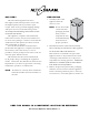
DELIVERy UNPACKINg This alto-Shaam appliance has been thoroughly tested and inspected to ensure only the highest quality unit is provided. Upon receipt, check for any possible shipping damage and report it at once to the delivering carrier. See Transportation Damage and Claims section located in this manual. This appliance, complete with unattached items and accessories, may have been delivered in one or more packages.
installation SAFETy PROCEDURES AND PRECAUTIONS Knowledge of proper procedures is essential to the safe operation of electrically and/or gas energized equipment. In accordance with generally accepted product safety labeling guidelines for potential hazards, the following signal words and symbols may be used throughout this manual. DANgER Used to indicate the presence of a hazard that wILL cause severe personal injury, death, or substantial property damage if the warning included with this symbol is ignored.
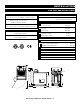
installation A S F - 7 5 E S pecifications dimensions exterior (h x w x d) ASF-75E without lifts or filtration 42" x 24-13/16" x 37-7/16" (1065mm x 629mm x 950mm) ASF-75E with lifts and filtration 44-3/16" x 24-13/16" x 38-11/16" (1121mm x 629mm x 983mm) basket dimensions (h x w x d) 6" x 9-3/16" x 14-3/16" (152mm x 232mm x 337mm) capacity SHORTENING/OIL: 73 lb (33 kg) maximum Load capacity: 13 lb (6 kg) maximum weight est.
installation A S F - 6 0 E S pecifications dimensions exterior (h x w x d) 44-3/8" x 15-3/4" x 33-5/8" (1127mm x 400mm x 854mm) basket dimensions (h x w x d) 5-3/16" x 5-7/8" x 13-13/16" (131mm x 149mm x 351mm) OPTIONS Fry Pot Cover Banking Strip (1 strip req’d for every 2 banked units) 1010991 Mobile Oil Caddy TO-28359 23-3/8" (592mm) 33-5/8" (853mm) 2-7/8" (72mm) El e c tri c F ryer Operati on & C are Manual • 4 ° 15-3/4" (400mm) 36-11/16" (931mm) ( l x w x h) 31-9/16" (802mm) Electrical Conne
installation DANgER DANgER IMPROPER INSTALLATION, ALTERATION, ADJUSTMENT, SERvICE, OR MAINTENANCE COULD RESULT IN SEvERE INJURy, DEATh, OR CAUSE PROPERTy DAMAGE. READ ThE INSTALLATION, OPERATING AND MAINTENANCE INSTRUCTIONS ThOROUGhLy BEFORE INSTALLING OR SERvICING ThIS EQUIPMENT. AvERTISSEMENT : UNE INSTALLATION, UN AJUSTEMENT, UNE ALTÉRATION, UN SERvICE OU UN ENTRETIEN NON CONFORME AUX NORMES PEUT CAUSER DES DOMMAGES À LA PROPRIÉTÉ, DES BLESSURES OU LA MORT.
installation SITE INSTALLATION 1. It is the responsibility of the installer to verify that this fryer installation is in compliance with the specifications listed in this manual and with local code requirements. 9. 2. Hood installation is required. 10. 3. Both cooking and cleaning functions require unobstructed access. The frypot, control panel, and front access door must be maintained free from obstruction. The access door must be accessible for service and maintenance. 4.
installation ventilation DANgER Installation, air ventilation requirements, and service work must be in accordance with all local codes and must be performed by a qualified service technician. An adequate ventilation system is required for commercial cooking equipment. Information may be obtained by writing to the National Fire Protection Association, Batterymarch Park, Quincy, MA 02269. When writing refer to NFPA No. 96.
installation restraint requirements - mo b ile equipment The fryer must be supplied with a connector that complies with all state and local installation codes. Any appliance that is not furnished with a power supply cord but that includes a set of casters must be tethered. Adequate means must be provided to limit the movement of this appliance without depending on or transmitting stress to the electrical conduit. The following requirements apply: 1. Casters must be a maximum height of 4-inches (102mm). 2.
installation electrical requirements DANgER DANgER To avoid electrical shock, this appliance MUST be adequately grounded in accordance with local electrical codes or, in the absence of local codes, with the current edition of the National Electrical Code ANSI/ NFPA No. 70. In Canada, all electrical connections are to be made in accordance with CSA C22.1, Canadian Electrical Code Part 1 or local codes. An electrical wiring diagram is located in the front access door of the fryer.
installation electrical installation 1. Refer to the nameplate on the front of the fryer. Verify the electrical service power. Voltage and phase must match the nameplate specifications and available electrical service amperage must meet or exceed the specifications listed. NOTE: W ire gauge, insulation type and temperature rating, as well as type, size and construction of conduit, must meet or exceed applicable specifications of local codes and of the National Electrical Code.
operation oil / shortenin g requirements OIL/SHORTENING REQUIREMENTS The ASF-75E requires 73-pounds (33 kg) of oil or shortening in the frypot and the ASF-60E requires 62-pounds (28 kg) of oil or shortening. Use only quality, high-grade oil/shortening in the fryer. The high moisture content of many lower grade shortening will result in excessive foaming and boil over. The cold oil/ shortening level requirement for the fryer is indicated below.
operation ASF-60E, 120V kettle drain selector element hi-limit reset closed open element hi-limit alarm oil hi-limit reset master power switch ASF-75E, 120V with filtration kettle drain selector open nozzle connection closed nozzle kettle selector element oil hi-limit hi-limit reset reset pump element master hi-limit power alarm switch ASF-75E, 120V open kettle drain selector oil element hi-limit hi-limit reset reset closed element master hi-limit power switch alarm El e c tri c F ry e r O
operation b oil - out procedure NOTE: Perform an initial Boil-Out to clean and NOTE: Manual Boil-Out can only be performed sanitize the fryer before operating. Carbonized deposits along with an accumulation of oil will eventually build-up on the interior of the frypot as well as fryer accessories. It is important to periodically remove these deposits, not only to maintain fryer efficiency, but also to provide the highest product quality.
operation b oil - out procedure Drain the oil. Rinse fry pot with a small amount of water. CAUTION KEEP A CONTAINER OF COLD wATER ON hAND DURING BOIL-OUT IN CASE OF BOIL-OvER. IF BOILOvER IS IMMINENT, IMMEDIATELy TURN OFF MASTER POwER SwITCh AND POUR COLD wATER INTO FRyPOT TO QUICKLy REDUCE SOLUTION TEMPERATURE. 8. Turn the Master Power Switch (located behind the front access door) to the “ON” position and press the CONTROL RESET. 9. To enter Boil Mode, press and hold the P key 3 seconds.
operation start up & g eneral operation NOTE: Perform an initial Boil-Out to clean NOTE: and sanitize the fryer station before operating. for your protection The fryer station is furnished with a hi-limit safety shutoff that will disengage the control if the frying compound temperature in the frypot would ever exceed 1. Service is to be performed by an authorized 406°F (208°C). The high limit switch will pop Alto-Shaam service agent. out and the kettle will no longer heat. In this 2.
operation cleanin g & maintenance DANgER DISCONNECT UNIT FROM POwER SOURCE bEFORE CLEANINg OR SERVICINg. THOROUGHLY CLEAN DAILY The cleanliness and appearance of this unit will contribute considerably to operating efficiency and savory, appetizing food. Good equipment kept clean works better and lasts longer. 1. Disconnect unit from power source, and let cool. 2. R emove all detachable items. Clean these items separately with a good grease solvent or commercial detergent. Rinse well and dry. 3.
operation oil filtration instructions (for units with installed option) Careful observation of the finished food product will help determine optimal filtering frequency. Filtering the cooking oil at regular intervals will help ensure food quality. FOR BEST RESULTS: Do not allow the temperature of the oil to decrease below the “Idle Mode” temperature of 250°F (121°C) when filtering. If filtering at the end of the day, pump oil back into the kettle while still hot.
operation oil filtration instructions (for units with installed option) FILTER REPLACEMENT 1. With the DRAIN in the “closed” position, pull the trolley from the fryer and disconnect the hose from the fryer. Use optional trolley handle if available, or take care when pulling trolley from fryer as it has sharp edges. (Contact factory for optional trolley handle information.) 2. Pushing down on filter frame 4 clip, pull side of filter cartridge A closest to clip upwards.
operation oil filtration instructions (for units with installed option) FILTER CLEANING & MAINTENANCE NOTE: M ake certain to use hand protection when working with hot surfaces. REUSABLE MESH FILTER OPTION: Clean the reusable mesh filter (FI-27014) by spraying thoroughly with hot water. DO NOT clean in the dishwasher. DO NOT use detergents to clean. Detergents and detergent residues will significantly reduce the life of oil and shortening products.
operation oil filtration instructions (for units with installed option) CLEANING & MAINTENANCE oil discard hose OPTION: The oil discard hose option (HO-27686) is available as an option to assist both the boil-out and filtration operation. The drain can be placed in the “open” or “closed” position as required. Disconnect hose following use and return the selector to the “kettle fill” position.
delu x e control operation panel identification 1 2 3 4 5 6 7 8 9 1. 2. 3. 4. 5. 6. LED display Hold indicator Heat indicator Melt cycle indicator Program indicator PRODUCT KEY INDICATOR LIGHTS: Illuminate during active cook cycle or programming mode. 9. Feature keys A. On/Off key B. Scan key: Shows time left between recipe / baskets C. Enter key: Used while entering your own menu / time. D. Temp toggle clear key E. hold key: Displays remaining hold time F.
delu x e control operation operatin g the control Start a Cook Cycle Product Key Press any product key to start a cook cycle. If the key is Start a Cook Cycle programmed, the cooking time will be displayed and Press any product key to start a cook cycle. If the key will immediately start to count down in minutes is programmed, the cooking time will be displayed and seconds. DONE will display when the cook cycle and will immediately start to count down in minutes has ended. and seconds.
delu x e control operation Check Product Counts To Check Product Counts : press and hold the P key for Press and hold the P key for 3 seconds. COUNTS will 3 seconds. COUNTS will be displayed. be displayed. Press the the P 1 willwill be displayed then the number Press P key. key.PROD PRODT be displayed then the of cooks that were completed on that key. To see theTo number of cooks that were completed on that key.
delu x e control operation Display Descriptions (continued) Operating Instructions Controller in Operating OperatingMode. Mode. The actual vat Controller is is in Actual vat temperature temperature more thanbelow 10 degrees below the prois more thanis10 degrees the programmed vat grammed vat temperature. temperature. Controller’s probeisiseither eitheropen open shorted. Display Controller’s probe oror shorted. Display will will accompanied audible alarm shorted.
delu x e control operation P roduct K e y pro g rammin g ( continued ) Type in thethe Type in1177224 4using using product keys. thethe product keys.Press Press key. PP key. Depending on model, you can either press the P key to change all programmable settings or you can scroll using the arrow keys to any of the specific options. Press the P key. Press the P key. Press the key Press thePPkey. key.All Allproduct product LEDs will light key LEDs will up. light up. program A Product PROGRAM A PRODUCT Key.
delu x e control operation P roduct K e y pro g rammin g ( continued ) Eitherpress pressanother another product Either product key to toprogram programand and repeat key repeat thethe programminginstructions, instructions, programming or continue by pressing the down or continue by pressing the arrow downkey. arrow key. Set Global Temperature. Press GLOBAL the P key. TEMPERASET TURE. Press the P key. SET TEMP,then then Actual Temp SET TEMP, Actual Temp will bedisplayed. displayed.
delu x e control operation s y stem pro g rammin g Enter System Programming ENTER SYSTEM PROMode. Press andMODE. hold the P GRAMMING key 3 hold seconds. Pressfor and the P key for 3 SYSTEM CODE (3228) MANAGER Press thedown downarrow arrow key. Press the key. seconds. Type in33222 28 8using using Type in thethe product keys.Press Press product keys. thethe P key. P key. PROGRAM willbebe displayed. PROGRAM will displayed. Press the Press thePPkey. key. Pressthe thePPkey. key. Press set appliance mode.
delu x e control operation programming custom product and action alarm names to the library Enter ENTERlibrary LIBRARY PROProgramming Mode. GRAMMING MODE. Press and hold the P key for Press and hold the P key for 3 3seconds. seconds. Press thedown downarrow arrow key. Press the key. PROGRAM willbebe displayed. PROGRAM will displayed. Press the Press thePPkey. key. SYSTEM CODE (3228) MANAGER Typein in3322228 8using using Type thethe prodproduct keys.the Press the P key. uct keys. Press P key.
operation ALL SUggESTED FRyINg TIMES ARE bASED ON A FULL LOAD OF PRODUCT Remove ice crystals and ensure that food is dry before frying. Excessive water and ice can cause oil to splatter or overflow. Do not over fill the basket. Food needs to be surrounded by oil for best frying results. SU g g ES T ED FR y INg T IMES PROgRAM KEyS item minutes temperature display 1. Fries ( FROZEN ) 3:30 350°F (177°C) Fries 2. Chicken Nuggets ( FROZEN ) 3:30 350°F (177°C) Nuggets 3.
operation ALL SUggESTED FRyINg TIMES ARE bASED ON A FULL LOAD OF PRODUCT Remove ice crystals and ensure that food is dry before frying. Excessive water and ice can cause oil to splatter or overflow. Do not over fill the basket. Food needs to be surrounded by oil for best frying results.
service DANgER DISCONNECT UNIT FROM POwER SOURCE bEFORE CLEANINg OR SERVICINg. CAUTION ThIS SECTION IS PROvIDED FOR ThE ASSISTANCE OF QUALIFIED SERvICE TEChNICIANS ONLy AND IS NOT INTENDED FOR USE By UNTRAINED OR UNAUThORIZED SERvICE PERSONNEL. CAUTION IT IS RECOMMENDED ThIS APPLIANCE BE INSPECTED By A QUALIFIED SERvICE TEChNICIAN AT REGULAR INTERvALS AS PART OF A STANDARD KITChEN MAINTENANCE PROGRAM. ExTENDED limiTED frypOT wArrANTy alto-Shaam, Inc.
service control trou b leshootin g PROBLEM No power CAUSE Circuit breaker OFF Appliance not plugged in Defective 24VAC transformer No sound Button problem Inoperable speaker Frozen key PROBE is displayed Reading wrong temperature Not heating Inoperable key Defective temperature probe Probe not plugged in Defective temperature probe Defective element, relay, contactor or gas valve Defective controller SOLUTION Check and reset Plug in cord Replace transformer Replace controller Replace controller Unplug
service trou b leshootin g service 1. FRYER WILL NOT POWER-UP A. Make certain cord is plugged in and breaker is turned “ on .” B. Ensure the drain switch is turned to the “ closed ” position. C. Ensure the master switch is turned to the “ on ” position. 2. FRYER WILL NOT HEAT A. Ensure the gas valve is turned “ on .” B. Ensure the gas hose is connected. C. Ensure the hi-limit is not tripped. C. Ensure there is oil in the frypot. 3. PUMP WILL NOT RETURN OIL A.
ASF-60E w service ith automatic lifts 8 9 7 6 10 11 5 4 2 3 1 380415 ASF-60E Model assembly ITEM DESCRIPTION P/N QTY 1 Electric Control Assembly 380-415V 77108 1 2 Front Panel with Drain Pipe 5013786 1 3 Door Assembly 5008965 1 4 Control Panel Assembly 5014288 1 5 Drain Valve, 1-1/4" S.S.
A S F - 6 0 E w ith automatic A S F - 6 0 E service lifts 1 SEE NOTE 6 NOTE: 1012370 IS ONLY USED WITH NO LIFT UNITS.
A S F - 6 0 E service 5007792 valve-drain assembly ITEM P/N DESCRIPTION QTY 1 VA-28114 Valve-Ball, use with FT-28113 1 2 5008497 Weldment, Drain Cam 1 3 1008739 Bracket, Drain Switch Mount 1 4 SW-34246 Limit Switch 1 5 SC-28288 Screw, 10-24 x .
A S F - 6 0 E w ith automatic A S F - 6 0 E service lifts 5007518 lift assembly 5 6 ITEM P/N DESCRIPTION QTY 1 1008420 Guide Column 2 2 1008421 Guide Support 2 3 RD-28118 Rod, Lift Weld 2 4 MO-27011 Motor, Lift 2 5 1008419 Guide Pen 2 6 1008418 Bracket, Lift Motor Mount 2 7 PI-27539 Pin, 1/4" x 1-1/4", Clevis 4 8 PI-27540 Pin, Cotter 4 9 HL-28117 Basket Lift 2 10 SC-2661 Screw, Philips Truss 24 3 1 5008570 4 2 Drain Panel and Switches ITEM DESCRIPTION P/N
ASF-60E w service ith automatic lifts 7 1 2 6 12 13 11 9 10 5 8 4 5008656 ELEMENTS ASSY-ASF60E 208-220V ITEM PART NO DESCRIPTION 1 2 3 4 5 6 7 8 9 10 11 12 13 PP-28143 BK-27098 BK-27099 EL-34352 EL-34387 1008527 PI-27152 1009262 WS-23671 SC -27481 SC -25286 WS-22303 SC -26462 PIPE, 2-1/2” SC H-40 304 SS HINGE BLOCK WITH SECURITY PIN HINGE BLOCK WITHOUT ELEMENT 208-220V ELEMENT 208-220V W/TC GUARD, HEATER PIN, SECURITY ELEMENT GUARD WASHER, LOCK, #10, 18-8 S/S SCREW, 10-32 X 1/2” HEX HD, SS 1/
A S F - 6 0 E w ith automatic A S F - 6 0 E service lifts 16 15 13 R EV . D E SC R IP TIO N D A TE 14 11 5 3 6 7 19 17 25 18 2 22 4 10 24 12 9 20 21 1 ELECTRIC ASSY 440-480 ITEM PART NO DESCRIPTION 1 2 3 4 5 6 7 8 9 10 11 12 13 14 BASE-ASF-60 TRANSFORMER, 230V/24V, 50A TRANSFORMER, 440/480V T-BLOCK, MODULAR RELAY BOARD-ASF-DELUXE BRACKET, HI-LIMIT CONTROLLER CONTROLLER, HI-LIMIT, WIRE SET-ASF 60E 440-480V NO LIFT BEEPER 6-32 X 3/8 RD HD 8-32 x 1/4” PHIL SCREW SPACER, 7/16 FOR .
A S F - 7 5 E , service w ith filtration & lifts 3 6 5 7 2 1 4 8 See details for these assemblies on following pages: ITEM PART NO DESCRIPTION QTY 1 2 3 4 5 6 7 8 1 1 1 1 1 1 1 1 5009735 5009636 5009628 5009179 5008595 1009361 5009630 5008588 MOUNT-MOTOR AND ELECTRICAL PANEL, LOWER ASSY W/FILTRATION KETTLE, 208-220 DOOR CONTROL PANEL BACK PANEL LIFT ASSEMBLY FAT DRAWER ASSEMBLY El e c tri c F ry e r Operati on & C are Manual • 40
A S F - 7 5 E , w ith filtration A S F - 7 5 E service & lifts 4 2 ITEM 1 2 3 4 5 6 PART NO 5009177 1006303 RI-2097 MA-25734 1009689 RL-27690 3 Door Assembly DESCRIPTION DOOR MAGNET BRACKET #42 STAINLESS RIVET DOOR MAGNET ELEMENT LIFT BRACKET ELEMENT LIFT QTY 1 1 6 1 1 1 3 5 6 1 1 6 5 4 3 2 1 ITE M N O.
A S F - 7 5 E , service w ith filtration & lifts 5008595 CONTROL PANEL ITEM DESCRIPTION R EV . PART NO 1 2 3 4 5 6 7 5008594 5007396 IN-22985 PE-28090 WS-27045 NU-2296 PE-28110 A A WELDMENT-CONTROL PANEL ASSY-CIRCUIT BOARD INSULATION, 1/2” CERAMIC MAIN OVERLAY-WATLOW WASHER, # 8, LOCK WASHER NUT, HEX # 8-32 INSERT-MENU CARD D E SC R IP TIO N QTY A D D ED M EN U C A R D S D A TE A P P R O V ED 05/ 09/ 08 KRM 1 1 1 1 4 4 2 5 1 2 6 4 3 7 7 6 5 4 3 2 1 I TE M NO.
A S F - 7 5 E , w ith filtration A S F - 7 5 E service & lifts 6 10 10 4 14 1 8 16 17 17 12 16 17 17 10 11 10 7 2 9 15 3 5009636 Panel, lower assy w/ filtration ITEM DESCRIPTION 13 1009369 TT-34245 PA-27057 SW-34254 LI-34252 SW-34240 VA-28274 FT-28008 FT-28275 SC-22271 FT-28661 TE-28662 LI-34251 LI-3951 SW-33495 SC-26791 SC-28288 EB-28687 PANEL, FRONT LOWER THERMOSTAT, HI-LIMIT PLATE-LIGHT MOUNTING SWITCH, CAM, FOR SINGLE PHASE LIGHT PUMP, PUSH BUTTON PUSH BUTTON SWITCH-PUMP VALVE-BALL 1/
A S F - 7 5 E , service w ith filtration & lifts 4 1 3 5 2 5 5008588 fat drawer assembly ITEM PART NO DESCRIPTION 1 2 3 4 5 6 5008589 CS-27054 CS-27253 5008591 SC-26791 HO-27649 WLDMT-FAT DRAWER CASTER, 2” WHEEL CASTER, 2” WHEEL FILTER CARTRIDGE SCREW 10-32 X 1/4” PAN HEAD HOSE, FRYER FILTER El e c tri c F ry e r Operati on & C are Manual • 44 QTY 1 2 2 1 16 1
A S F - 7 5 E , w ith filtration A S F - 7 5 E service & lifts 32 31 30 23 19 22 21 17 20 26 32 26 23 31 18 19 15 18 26 16 26 21 20 24 14 16 14 22 8 15 1 4 26 2 25 2 5 28 7 17 3 4 8 27 6 29 3 6 30 24 5009735 mount-motor and electrical ITEM DESCRIPTION QTY 1 1 1 1 33 32 2 31 31 0 29 24 8 27 24 6 25 1 24 23 1 22 21 1 20 11 9 18 11 7 16 11 5 14 1 13 12 1 11 11 0 9 38 7 36 954 623 11 ITM 3 3 1 12 2 4 2 1 2 1 1 5 M O -3 44 6 9 5E W / S7 4 M O TO R - 23 0 V C E 1 SC
A S F - 7 5 E , service N o filtration or lifts 6 3 7 5 4 2 1 See details for these assemblies on following pages: ITEM PART NO DESCRIPTION QTY 1 2 3 4 5 6 7 1 1 1 1 1 1 1 5009634 5009217 5009628 5009179 5008595 5009645 1009361 MOUNT-MOTOR AND ELECTRICAL PANEL, LOWER ASSY KETTLE-75E, 208-220 BSC DOOR CONTROL PANEL-ASF-75 BASKET HANGER PANEL-BACK El e c tri c F ry e r Operati on & C are Manual • 46
A S F - 7 5 E , N o filtration A S F - 7 5 E or service lifts 4 2 5009179 ITEM 1 2 3 4 5 6 3 Door Assembly PART NO DESCRIPTION 5009177 1006303 RI-2097 MA-25734 1009689 RL-27690 DOOR MAGNET BRACKET #42 STAINLESS RIVET DOOR MAGNET ELEMENT LIFT BRACKET ELEMENT LIFT QTY 1 1 6 1 1 1 3 5 6 1 6 5 4 3 2 1 ITE M N O.
A S F - 7 5 E , service N o filtration or lifts 23 32 31 19 30 20 22 21 32 17 26 26 31 15 26 18 19 18 26 23 21 16 14 16 20 22 24 8 14 4 15 1 26 25 2 2 28 7 5 17 3 4 6 8 27 6 29 3 30 24 ITEM PART NO mount-motor & electrical DESCRIPTION 5 QTY 1 1009269 MOTOR PLATE 2 TN-33282 TRANSFORMER, 230V/24V,50A 1 3 BK-34372 T-BLOCK, MODULAR 1 4 BA-34490 RELAY BOARD ASF-60 1 5 FI-33406 FERRITE FILTER-CLAMP 2 6 BP-3567 BEEPER 1 7 SP-33901 SPACER, 7/16 FOR .125 HOLE IN .
A S F - 7 5 E , N o filtration A S F - 7 5 E or service lifts 5009217 ITEM PART NO 1 2 3 4 5 6 1009947 TT-34245 SW-34254 SC-22271 LI-3951 SW-33495 panel, lower assy DESCRIPTION QTY PANEL, FRONT LOWER NO FILTER THERMOSTAT, HI-LIMIT SWITCH, CAM, FOR SINGLE PHASE SCREWS,M4-0.7X6MM PHIL WHITE PILOT LIGHT 250V SWITCH-PUSH BUTTON SPST 1 1 1 2 1 2 4 4 3 5 1 4 4 2 6 5008595 CONTROL PANEL ITEM DESCRIPTION R EV .
A S F - 6 0 E service El e c tri c F ry e r Operati on & C are Manual • 50
A S F - 6 0 E service El e c tri c F ry e r Operati on & C are Manual • 51
A S F - 6 0 E service El e c tri c F ry e r Operati on & C are Manual • 52
A S F - 6 0 E service El e c tri c F ry e r Operati on & C are Manual • 53
A S F - 7 5 E service El e c tri c F ry e r Operati on & C are Manual • 54
A S F - 7 5 E service El e c tri c F ry e r Operati on & C are Manual • 55
A S F - 7 5 E service El e c tri c F ry e r Operati on & C are Manual • 56
A S F - 7 5 E service El e c tri c F ry e r Operati on & C are Manual • 57
TRANSPORTATION DAMAGE and CLAIMS 1. 2. 3. 4. 5. 6. 7. 8. all alto-Shaam equipment is sold F.O.B. shipping point, and when accepted by the carrier, such shipments become the property of the consignee. Should damage occur in shipment, it is a matter between the carrier and the consignee. In such cases, the carrier is assumed to be responsible for the safe delivery of the merchandise, unless negligence can be established on the part of the shipper.