® INSTALLATION and MAINTENANCE MANUAL QC-40 P R O C E S S I N G R E F R I G E R AT I O N S Y S T E M W 1 6 4 N 9 2 2 1 W a t e r S t r e e t ● P. O . B o x 4 5 0 ● PHONE: (262)251-3800 (800)558-8744 U . S . A ./ C A N A DA ● Menomonee Falls, Wisconsin 53052-0450 ● U.S.A. ● FAX: (262)251-7067 (800)329-8744 U . S . A . www.alto-shaam.
quickchiller Processing Refrigeration System ® I N S TA L L AT I O N & M A I N T E N A N C E M A N U A L Ta b l e o f C o n t e n t s - Q C - 4 0 1.0 GENERAL INFORMATION & INSTALLATION 1.1 Introduction . . . . . . . . . . . . . . . . . . . . . . . . 1.2 Scope of the Manual . . . . . . . . . . . . . . . . . . 1.3 Equipment Description . . . . . . . . . . . . . . . . 1.4 Equipment Supplied . . . . . . . . . . . . . . . . . . 1.5 Receipt and Unpacking . . . . . . . . . . . . . . . . 1.6 Installation . . . . .
1.0 — General Information and Installation 1.1 INTRODUCTION 1.4 EQUIPMENT SUPPLIED The Alto-Shaam® Quickchiller is a processing refrigeration system designed to rapidly and uniformly cool hot foods through the "chilling danger zone" of 140° to 40°F (60° to 4°C) in two hours or less. Fast cooling minimizes microbial activity, thereby controlling quality and sanitation in prepared foods. As a result, a five-day storage life is achieved.
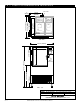
1.0 — General Information and Installation ELEC. BOX 19-1/4" 1" (25mm) ELECTRICAL ENCLOSURE 39-3/4" (1010mm) 37-1/4" (946mm) 35" (889mm) (489mm) 1/2 HP 1 HP CIRCUIT BREAKER – TOP VIEW – 38-1/2" (978mm) 30-3/8" (772mm) CPU Enclosure 6" (152mm) 36-3/4" (933mm) ‹ (597mm) 70-1/4" (1784mm) 2-1/4" (57mm) 23-1/2" ‹ FIG. 1.0 ITEM: Quickchiller Assembly Drawing MODEL: QC-40 Quickchiller™ Processing Refrigeration System DATE: 05/03 SCALE: N.T.S.
1.0 — General Information and Installation 1.5 RECEIPT AND UNPACKING Upon receipt of the Alto-Shaam ® Quickchiller, note any crate markings for special instructions and check for crate damage. IMMEDIATELY notify the carrier if there appears to be damage to the equipment. The chiller is shipped from the factory, securely fastened to a single shipping pallet and protected by an external wrapping. Carefully remove all external wrappings and other protective coverings.
1.0 — General Information and Installation 1.6.6 ELECTRICAL: The Quickchiller must be installed by a qualified electrician. This appliance must be branch circuit protected with proper ampacities in accordance with the wiring diagram located in this manual. In the U.S.A., the chiller must be properly grounded in accordance with the National Electrical Code and applicable local codes.
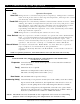
2.0 — Control Set-Up and Operation 2.1 START-UP PROCEDURES remains in the display longer than 60 seconds, the locked control panel cover must be opened and the yellow reset button pressed ONCE. Relock the control panel and enter the correct password to gain access to the User Setting Menu screen. 2.1.1 Place the branch circuit breaker (main panel) in the ON position. Then place the Quickchiller circuit breaker in the ON position. 2.1.2 The Main Menu screen must appear on the Control display (see figure 2.
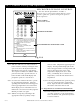
2.0 — Control Set-Up and Operation MICROPROCESSOR CONTROL ® ™ QUICK CHILL ................... HOLD FOOD ..................... DEFROST FOOD ............... PRINT REPORT................. A B C D — 0 The Alto-Shaam ® Quickchiller ™ includes a microprocessor control panel which utilizes a menu screen to guide the operator through all operation mode sequences. MENU SCREEN — MAIN MENU SHOWN A B CONTROL KEYBOARD C D CE CHILLING or HOLDING 1. LOAD FOOD.
2.0 — Control Set-Up and Operation CONTROL MODE OVERVIEW Ta b le 2.4.1 Mode Operation Description Auto Chill Refrigeration is controlled only by the food probe(s). Refrigeration continues until all food probes achieve chill setpoint temperature, whereupon the control automatically enters HOLD Mode. Timed Chill Refrigeration is controlled by chill time entered and the cabinet air sensor. While chilling, the cabinet air temperature may become exces-sively cold prior to chill time expiration.
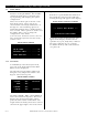
2.0 — Control Set-Up and Operation 2.5 MAIN MENU The main menu is the starting point for all functions of the Quickchiller. This includes starting the hold, defrost, and chill cycles; report printing; and changing the system configuration. 2.5.2 Open Door If the door is opened while the chiller is in the hold mode, a buzzer will sound and a warning message will appear in the display. DOOR OPEN WARNING SCREEN There are four main options shown on the main menu screen.
2.0 — Control Set-Up and Operation 2 . 6 OPERATION WITH FOOD PRODUCT Stage 1: Stage 4: Prior to introducing product to the cabinet, the unit should be operated in the timed chill mode for thirty minutes. This procedure will reduce the temperature of the interior components and the cabinet air sufficiently to be able to accept hot food products. Upon satisfaction of the Chill Mode selected, the system will revert to the hold mode.
2.0 — Controls, Operation and Start-Up 2.8 HARDWARE NOTES AT- A - G L A N C E QC-40 CONTROL SETTINGS NOTE: Refer to Operation and Procedure Guide, Section 9.0. SERIAL PRINTER: PRINTER . . . . . . . . . . . . . . . . Printer Interface Baud Rate Stop Bits Printing Delay Sample Period, min. Print Grid Spacing Print Grids Printer Columns BUZZERS/TIMEOUTS . . . . . . . Probe Mute Time, sec. Chill Done Time, sec. Are-U-Sure Time, sec. DefrstDone Time, sec.
5.0 — Cleaning & Maintenance 5 . 1 INTRODUCTION To insure trouble free operation and the highest level of sanitation control, periodic cleaning and maintenance is required. The maintenance system should be aimed at maximizing the efficient utilization of maintenance personnel, minimizing down time, and providing the orderly acquisition of spare parts for support. If already established at the location site, perform scheduled maintenance in accordance with the standards in the Maintenance Index Plan.
5.0 — Cleaning & Maintenance 5.6 MONTHLY COMPRESSOR AND CONDENSER MAINTENANCE 5.5 EVAPORATOR CONDENSATE DRAIN HOSE INSPECTION AND CLEANING 1. Every 4-6 months, the evaporator coil and condensate drain hose should be inspected for blockage due to spilled food and sauces which can accumulate about the base of the coil and clog the entrance to the drain hose. Keep the condenser coils free of dust and debris to insure proper air circulation and cooling of the refrigeration system. 1.
R a c k M a n a g e m e n t Tr o l l e y S y s t e m 1 0 • 1 0 C o m b i t h e r m a n d 1 0 • 1 8 W Wa r m e r 7 1 2 6 5 3 8 4 10 9 11 17 14 13 12 ON F OF 16 ON F OF 15 FIG. 1.4.1 DESCRIPTION QUAN. PT. NO. Pan Rack Assembly 1 15637 1. Base Frame 1 14584 2. Handle Assembly 1 3. Wheels 4. DESCRIPTION QUAN. PT. NO. Base Trolley Assembly 1 15635 9. Guide Block 1 BK-23020 14184 10. Guide Screw 2 SC-2713 4 WH-23034 11.
R a c k M a n a g e m e n t Tr o l l e y S y s t e m 7 • 1 4 C o m b i t h e r m a n d 1 0 • 1 8 W Wa r m e r 7 1 2 6 5 3 4 8 10 9 11 17 14 13 12 ON F OF 16 ON F OF 15 FIG. 1.4.2 DESCRIPTION QUAN. PT. NO. Pan Rack Assembly 1 15639 1. Base Frame 1 14586 2. Handle Assembly 1 3. Wheels 4. DESCRIPTION QUAN. PT. NO. Base Trolley Assembly 1 15635 9. Guide Block 1 BK-23020 14184 10. Guide Screw 2 SC-2713 4 WH-23034 11.
R a c k M a n a g e m e n t Tr o l l e y S y s t e m 1 0 • 1 8 C o m b i t h e r m a n d 1 0 • 1 8 W Wa r m e r 1 7 6 2 5 3 4 8 10 9 11 17 14 13 12 ON F OF 16 ON F OF 15 FIG. 1.4.3 DESCRIPTION QUAN. PT. NO. Pan Rack Assembly 1 15638 1. Base Frame 1 14585 2. Handle Assembly 1 3. Wheels 4. DESCRIPTION QUAN. PT. NO. Base Trolley Assembly 1 15635 9. Guide Block 1 BK-23020 14184 10. Guide Screw 2 SC-2713 4 WH-23034 11.
3.0 — Control & Component Parts Identification 3 . 1 — Q C - 4 0 C O N T R O L PA R T S L I S T, s e e p a g e 1 3 ITEM DESCRIPTION QUAN. PT. NO. CPU ENCLOSURE ASSEMBLY 1 15034 1. LCD Board Assembly 1 BA-33304 2. Door Lock 1 LK-23046 3. Door Gasket 5. Buzzer 6. Dip Switch 7. EPROM 8. PFI Adjust, P12 9. Write Protect Jumper 4' (1219mm) 10. I/O Cable 11. J10 "—" Pin 12. CPU Board 13. Keys, Door Lock 1 GS-2019 BA-33100 LK-24176 3 .
#8402 QC-40 INSTALLATION & MAINTENANCE MANUAL PG . ® DWN BY: LRP MENOMONEE FALLS, WISCONSIN, U.S.A. REV: SCALE:3/8" = 1" 10/31/95 DATE: Quickchiller™ Processing Refrigeration System FIG. 3.
3.0 — Control & Component Parts Identification 2 8 7 4 GND +5V SWITCH DOOR CABLE I/O L1 +5 VDC NC CPU COMPRESSOR POWER SC-15 BUSS FUSE POWER IN 1 24 VAC RELAY 2A 2 LH OUTPUT CRYDOM L1 ASSEMBLED IN MEXICO 10104 A2425 RH INPUT 4 4 1 3-4 5-6 L1 3-4 5-6 L1 1 3 6 RIGHT HAND FANS 1-2 LINE LEFT HAND FANS LOAD 2X.0047uF +20%/25% (Y) C-3X1uF(X2)MP/MKT L-2X(1.86+1.86) mH R-1X1M OHM LINE CURTIS RFI FILTER F1300AA01 INDUSTRIES INC. 1A/115-250 VAC 50/60 HZ.
3.0 — Parts Identification 3.4 — QC-40 - REFRIGERATION PARTS LIST ITEM DESCRIPTION QUAN. PT. NO. 1. Large Condensing Unit 1 Cosp RUT910 2. Small Condensing Unit 1 Cosp RUT550 3. Filter Dryer 2 Cosp RWFD02 4. Sight Glass 2 Cosp RWSG03 5. Solenoid Valve 2 Cosp RWSV03 6. Solenoid Coil 2 Cosp RWSC02 7. Evaporator Coil 1 Cosp RWE311 8. Evaporator Blower Motor 3 MO-33670 9. Expansion Valve (1/4 ton) 1 Cosp RWEV27 10 Expansion Valve (1/2 ton) 1 Cosp. RWEV30 3.
4.0 — Diagnostic and Repair Procedure — CONTROL 4.1 INTRODUCTION 4.2.1 SOLENOID CHECK: The relays, which control the compressors, fans, solenoids, and heaters, can be individually controlled by the microprocessor control set in a manual mode. The following test will verify that these components are being controlled and will verify the operational integrity of the relays and fuse sets. 4.2 Press button 1 and button 2 on the numeric keyboard several times.
4.0 — Diagnostic and Repair Procedure — CONTROL 4 .3 CONDENSING UNITS The condensing units operate only when the system is in a cooling mode and the food storage compartment requires a decrease in temperature. If it appears the condensing units are not functioning properly and the General Diagnostic Procedure (4.2.4) on the preceding page was unable to pinpoint the specific cause, the following steps should be taken for further diagnosis.
4.5 TROUBLE-SHOOTING GUIDELINES - CONTROL PROBLEM POSSIBLE CAUSE Alphanumeric display is blank. If power is connected to the unit and the main circuit breaker is on, the display on the control should be illuminated with a green tinged background. Control needs to be reset. Unresponsive control. If the control does not respond to operator key presses or the screen on the display appears frozen or sluggish. Control needs to be reset. Power failure threshold is set too low. Control board is faulty.
4 . 0 — D i a g n o s t i c a n d R e p a i r P r o c e d u r e — R E F R I G E R AT I O N This chart is provided for the assistance of refrigeration technicians only and is not intended for use by untrained or unauthorized service personnel. If your Alto-Shaam Quickchiller is not operating properly, check the following BEFORE calling your Authorized Alto-Shaam Service Agent: ➾ Check the power flow to the unit. Fuses OK? Breakers OK? DO NOT ATTEMPT TO REPAIR OR SERVICE THE QUICKCHILLER BEYOND THIS POINT.
4 . 0 — D i a g n o s t i c a n d R e p a i r P r o c e d u r e — R E F R I G E R AT I O N DOOR SWITCH I/O CABLE LEFT HAND FANS L1 L1 3-4 1-2 5-6 3-4 HEATERS HEATERS 1-2 L1 1 2 3 L1 4 SOLINOID 5 6 RH L1 COMPRESSOR LH NC L1 RELAY ACCESSORY FUSES 5-6 GND +5V +5 VDC CPU POWER RIGHT HAND FANS POWER IN 24 VAC INDICATOR LIGHTS I/O PORT ITEM: Relay Board MODEL: QC 40 Quickchiller Processing Refrigeration System Fig. 4.5.1 DATE: 04/04/97 ® MENOMONEE FALLS, WISCONSIN 53051, U.
INSTALLATION & MAINTENANCE MANUAL 4.0 — Diagnostic and Repair Procedure — ELECTRICAL #8402 QC-40 PG .
PG . 26 INSTALLATION & MAINTENANCE MANUAL 4.
TR ANS P O RTAT I O N DAMAGE and CLAIMS LIMITED WARRANTY All Alto-Shaam equipment is sold F.O.B. shipping point, and when accepted by the carrier, such shipments become the property of the consignee. Should damage occur in shipment, it is a matter between the carrier and the consignee. In such cases, the carrier is assumed to be responsible for the safe delivery of the merchandise, unless negligence can be established on the part of the shipper. 1.