Combination Oven / Steamer 10•10 MAR I N E Electric ML • I N STALLATION • OPERATION • MAI NTENANCE W 1 6 4 N 9 2 2 1 W a t e r S t r e e t • P. O . B o x 4 5 0 • M e n o m o n e e F a l l s , W i s c o n s i n 5 3 0 5 2 - 0 4 5 0 U S A PHONE: 262.251.3800 • 800.558.8744 USA/CANADA FAX: 262.251.7067 • 800.329.8744 U.S.A. ONLY WEBSITE: www.alto-shaam.com PRINTED IN U.S.A.
COMBITHERM ® TABLE OF CONTENTS ELECTRIC INSTALLATION SERVICE SECTION Delivery & Unpacking . . . . . . . . . . . . . .1 SERVICE VIEW • OVEN EXTERIOR . . . . . .34 Safety Procedures & Precautions . . . . . .2 Options & Accessories . . . . . . . . . . . . . .3 Basic Installation Site Requirements . . . . . .4 Ventilation Requirements SERVICE VIEW• OVEN INTERIOR . . . . . . .35 SERVICE VIEW• SIDE PANEL ACCESS . . . .36 . . . . . . . . . . .4 Positioning On Site . . . . . . . . . . . . . . . .
C O M B I T H E R M ® I N S TA L L AT I O N DELIVERY UNPACKING This Alto-Shaam appliance has been thoroughly tested and inspected to insure only the highest quality unit is provided. Upon receipt, check for any possible shipping damage and report it at once to the delivering carrier. See Transportation Damage and Claims section located in this manual. This appliance, complete with unattached items and accessories, may have been delivered in one or more packages.
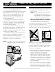
SAFETY PROCEDURES AND PRECAUTIONS Knowledge of proper procedures is essential to the safe operation of electrically and/or gas energized equipment. In accordance with generally accepted product safety labeling guidelines for potential hazards, the following signal words and symbols may be used throughout this manual. Used to indicate the presence of a hazard that will cause severe personal injury, death, or substantial property damage if the warning included with this symbol is ignored.
C O M B I T H E R M ® O P T I O N S & AC C E S S O R I E S OPTIONS & ACCESSORIES AutoClean ™ A fully automated oven cleaning function with 4 levels of cleaning. (Not available on S-Control models). ➥ 5001298 FACTORY INSTALLATION ONLY ➥ CLEANER ➥ RINSE AGENT — FOUR — (4) CONTAINERS / CASE ; (4) FOUR CHICKEN GREASE TRAY 1 GAL ( C . CONTAINERS / CASE ; WITH DRAIN : 1 3,79 GAL ( C .
C O M B I T H E R M ® I N S TA L L AT I O N BASIC INSTALLATION SITE REQUIREMENTS H O O D I N S TA L L AT I O N I S R E Q U I R E D • Installation surface must be level. • Do not install adjacent to flammable surfaces. DO NOT store or use any flammable liquids or allow flammable vapors in the vicinity of any appliance. • Deep fat fryers or similar heat producing equipment must not be installed in the immediate vicinity of the hand shower.
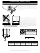
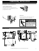
C O M B I T H E R M ® I N S TA L L AT I O N POSITIONING ON SITE removing the oven from the pallet for positioning on ➤Before site, it is important to remove the drip tray to prevent damage to the tray caused by the lifting forks. The drip tray is fastened to the bottom of the oven with three sheet metal screws as illustrated. Lift the oven from the pallet with a fork lift or pallet lift truck positioned at the front of the oven.
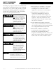
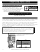
INSTALLATION REQUIREMENTS ■ Do not install oven adjacent to flammable 4" (102mm) surfaces. Strictly observe all local fire safety regulations. ■ In order to ensure proper ventilation, a minimum distance of at least 6-inches 18" (46cm) (152mm) must be kept from the control panel side [ LEFT ] of the oven and any adjoining surfaces. 4" (102mm) NOTE: In addition to ventilation RETRACTABLE DOOR OPTION: requirements, additional clearance 6-1/2" (165mm) is needed for service access.
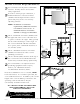
C O M B I T H E R M ® I N S TA L L AT I O N ASSEMBLY REQUIREMENTS HAND SHOWER HOLDER Fasten the hand shower holder in the holes provided on the oven using the three (3) screws packaged with the holder. DRIP TRAY Fasten the drip tray to the bottom of the oven using the three (3) screws as illustrated. FAILURE TO PROPERLY INSTALL THE DRIP TRAY CAN OR WILL C AU S E M A J O R E Q U I P M E N T DAMAGE AND WILL RESULT IN A LEAKAGE HAZARD THAT CAN CAUSE PERSONAL INJURY.
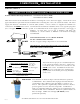
C O M B I T H E R M ® I N S TA L L AT I O N WATER SUPPLY C O N N E C T TO P OTA B L E ( D R I N K A B L E ) C O L D WAT E R O N LY WATER PRESSURE REQUIREMENTS: M I N I M U M 30 PSI (2 BAR) MAXIMUM 90 PSI (6 BAR) Flush the water line at the installation site before connecting the oven to the water supply. A shut-off valve and approved back-flow preventer must be installed when connecting the oven to the cold water intake. The water supply line must be a minimum of 3/4-inch (NPT) (19mm).
C O M B I T H E R M ® I N S TA L L AT I O N WATER DRAINAGE The oven must discharge through an indirect waste pipe by means of an air gap. The drain thread is 1-1/4-inch (32mm) NPT. A union is required. Install a 1-1/4-inch (32mm) diameter drain line. The drain line must always be a positive gradient away from the Combitherm oven and not more than 12-inches (305mm) before an air gap. NOTE: In the U.S.A.
C O M B I T H E R M ® I N S TA L L AT I O N STACKING INSTALLATION Stacking Combitherm ovens require two (2) water connections, two (2) drain connections, and two (2) electrical connections. UNION Intake 1" (25,4mm) 3/4" (19mm) 1-1/4" (32mm) UNION WATER INTAKE DRAIN RESTRAINT REQUIREMENTS — MOBILE EQUIPMENT Any appliance that is not furnished with a power supply cord but that includes a set of casters must be provided with a tether.
C O M B I T H E R M ® I N S TA L L AT I O N ELECTRICAL INSTALLATION ELECTRICAL CONNECTIONS MUST BE MADE BY A QUALIFIED SERVICE TECHNICIAN IN ACCORDANCE WITH APPLICABLE ELECTRICAL CODES. An electrical wiring diagram is located behind the control panel on the left side of the oven. The oven must be installed by a qualified electrician. This appliance must be branch circuit protected with proper ampacities, in accordance with the wiring diagram located in the electrical compartment of the oven.
A D D I T I O N A L T E C H N I C A L D ATA MODEL ➜ 10•10 M L counter Type of Oven oven stand Pan INCHES 10: 12" x 20" 10: 18" x 13" Capacity GASTRONORM Side Rack INCHES 10: GN 1/1 2-5/8 Spacing (MILLIMETERS) (65mm) Interior 23-1/2 INCHES Width ( MILLIMETERS ) Interior INCHES Depth ( MILLIMETERS ) Interior INCHES Height ( MILLIMETERS ) (596) 21-1/16 (535) 27 (685) Noise The noise emission level related to the workplace is lower than: 70 dBA Level Spray Hose 81-inches Length (2050m
C O M B I T H E R M ® I N S TA L L AT I O N INSTRUCTIONS TO BE PROVIDED TO OWNER/OPERATOR ■ INITIALS / DATE Owner/operator has been instructed on proper method of flushing the steam generator and safe procedures for handling the steam generator drain cap. ■ Owner/operator has been instructed on the importance of cleaning the oven along with proper cleaning procedures including automatic steam generator flush, daily cleaning of the interior, and monthly decalcification.
ELECTRIC COMBITHERM INSTALLATION CHECKLIST ® Use this list as a final check of oven installation conformance. Damage directly attributed to improper set up, installation, or cleaning can invalidate warranty claims. CLEARANCES: All clearances must conform with the standards set by Alto-Shaam as indicated in the installation manual. Standards include a minimum 20” (50cm) clearance from any heat-producing device such as an open burner range, flat top grille, fryer, steamer, etc.
I M P O R TA N T S A F E T Y P R E C A U T I O N S For safe release of the cooking compartment steam, initially open the door approximately 2" (50mm) only. STEAM S t a n d behind the door as the hot steam is released. DO NOT USE THE ATTACHED HAND-HELD HOSE TO SPRAY ANYTHING OTHER THAN THE INTERIOR OF THE COMBITHERM OVEN COMPARTMENT. AT NO TIME SHOULD THE EXTERIOR OF THE OVEN BE STEAM CLEANED, HOSED-DOWN WITH THE HAND-SPRAYER, FLOODED WITH WATER, OR FLOODED WITH LIQUID SOLUTION OF ANY KIND.
C O N T R O L PA N E L I D E N T I F I C AT I O N POWER ON/OFF KEY STEAM MODE KEY RETHERM MODE KEY START / STOP KEY SUPERHEATED STEAM AND CONVECTION MODE KEY CONVECTION MODE KEY PROGRAMMED MENU KEY DELUXE MODELS ONLY PROGRAM INSTALL/EDIT KEY DELUXE MODELS ONLY CHEF FUNCTION KEY FUNCTION & OPERATING INDICATORS COOKING TEMPERATURE KEY CONTROL PANEL DISPLAY CORE TEMPERATURE KEY UP ARROW KEY QUICK PROGRAM KEYS TIME KEY DOWN ARROW KEY ADJUSTMENT KNOB DELUXE MODEL
C O N T R O L PA N E L I D E N T I F I C AT I O N POWER ON/OFF KEY Activates power to the oven and automatically fills the steam generator with water which will heat to a stand-by mode temperature of 150°F (65°C). The steam generator flush is also activated by pressing this key. START/STOP KEY Initiates all cooking mode functions and programmed procedures stored in memory. Stops an activated cooking mode or programmed procedure currently in progress, and exits Chef function key.
S - C O N T R O L PA N E L I D E N T I F I C AT I O N OFF POSITION Maintains oven in a stand-by mode. STEAM The oven will operate at a fixed steam temperature of 212° F (100°C). COMBINATION A combination of steam and convection heat to cook at a temperature between 86°F and 482°F (30°C to 250°C) to be set by the operator. CONVECTION Convection heat to cook without steam at a temperature between 86°F and 482°F (30°C and 250°C) to be set by the operator.
COMBITHERM® CLEANING & MAINTENANCE Preventive Maintenance In addition to the routine cleaning and maintenance procedures, there are several additional steps to be taken for both sanitation purposes and to keep the oven running at top operating efficiency. These additional safeguards will help prevent inconvenient down time and costly repairs. AT NO TIME SHOULD THE INTERIOR OR EXTERIOR BE STEAM CLEANED, HOSED DOWN, OR FLOODED WITH WATER OR LIQUID SOLUTION OF ANY KIND. DO NOT USE WATER JET TO CLEAN.
AU TO M AT I C S T E A M G E N E R ATO R F L U S H AT T H E S TA RT O F E AC H WO R K DAY STANDARD CONTROL DELUXE CONTROL STANDARD CONTROL DELUXE CONTROL Flushing the electric Combitherm steam generator on a daily basis helps to prolong the life of the steam generator heating elements and helps prevent the necessity of service requirements. The control provides this feature as an automatic function when the oven ON/OFF power key is pressed to the ON position at the start of each working day.
CLEANING AND PREVENTIVE MAINTENANCE PROTECTING STAINLESS STEEL SURFACES CLEANING AGENTS It is important to guard against corrosion in the care of stainless steel surfaces. Harsh, corrosive, or inappropriate chemicals can completely destroy the protective surface layer of stainless steel. Abrasive pads, steel wool, or metal implements will abrade surfaces causing damage to this protective coating and will eventually result in areas of corrosion.
COMBITHERM® CLEANING & MAINTENANCE RUBBER GLOVES AND PROTECTIVE EYE WEAR MUST BE WORN WHEN USING THE OVEN CLEANER. USE AUTHORIZED COMBITHERM L I Q U I D O V E N C L E A N E R O N LY Unauthorized cleaning agents may discolor or harm interior surfaces of the oven. Read and understand label and material safety data sheet before using the oven cleaner. Causes severe burns. Do not get in eyes, on skin, or on clothing. Do not wear contacts. Harmful or fatal if swallowed. Do not breathe mist.
CONTROL OPTION COMBITHERM® CLEANING & MAINTENANCE CONTROL D A I LY O V E N C L E A N I N G OPTION The Combitherm automatic cleaning function selects the proper temperature for each step of the cleaning process. 1. Remove all food scraps and residue from the oven drain. Close the oven door securely. Rotate the power knob to the cleaning symbol. THE OVEN WILL BEGIN THE FIRST STEP IN A TWO-STEP CLEANING CYCLE • 10 MINUTES at a steam temperature of 86°F (30°C) 2.
STANDARD CONTROL DELUXE CONTROL COMBITHERM® CLEANING & MAINTENANCE D A I LY O V E N C L E A N I N G STANDARD CONTROL DELUXE CONTROL D O N O T S P R AY C L E A N E R INTO A HOT OVEN. ALLOW THE OVEN TO COOL TO 150°F (60°C). The temperature in the display indicates the air temperature inside the oven compartment and not the interior walls of the oven. Always make certain to allow the oven walls to cool to a minimum of 150°F (60°C) before spraying the compartment with oven cleaner. 1.
COMBITHERM® CLEANING & MAINTENANCE STANDARD CONTROL DELUXE CONTROL A U T O M AT I C C L E A N I N G P R O G R A M The Combitherm automatic cleaning function selects the proper temperature for each step of the cleaning process. With the oven power on: PRESS THE CHEF FUNCTION KEY. ➡ Rotate the adjustment knob until the clean symbol is highlighted in the display. PRESS THE CHEF FUNCTION KEY.
CONTROL OPTION C O M B I T H E R M ® D E C A L C I F I C AT I O N CONTROL OPTION It is VERY important to decalcify the oven, particularly in areas with extremely hard water. PERFORM ONCE A MONTH in addition to the daily steam generator flush. WITH THE OVEN AT ROOM TEMPERATURE 1. Begin decalcification with the power switch in the OFF position. 2. Rotate the Steam Generator Drain Cap until water begins to flow from the four holes in the cap.
C O M B I T H E R M ® D E C A L C I F I C AT I O N CONTROL TURN THE SELECTION KNOB TO THE STEAM POSITION. OPTION THE WATER IN THE STEAM GENERATOR WILL BEGIN TO HEAT. ALLOW THE OVEN TO REMAIN IN THIS POSITION FOR A MINIMUM PERIOD OF 10 MINUTES TO DECALCIFY THE STEAM GENERATOR. DO NOT TURN THE TIMER ON. Severe burns could occur.
STANDARD CONTROL DELUXE CONTROL C O M B I T H E R M ® D E C A L C I F I C AT I O N It is VERY important to decalcify the oven, particularly in areas with extremely hard water. STANDARD CONTROL DELUXE CONTROL PERFORM ONCE A MONTH in addition to the daily steam generator flush. WITH THE OVEN AT ROOM TEMPERATURE 1. Begin decalcification with the power switch in the OFF position. 2. Rotate the Steam Generator Drain Cap until water begins to flow from the four holes in the cap.
C O M B I T H E R M ® D E C A L C I F I C AT I O N STANDARD CONTROL DELUXE CONTROL PRESS THE ON/OFF POWER KEY TO THE ON POSITION. THE WATER IN THE STEAM GENERATOR WILL BEGIN TO HEAT. ALLOW THE OVEN TO REMAIN IN THIS POSITION FOR A MINIMUM PERIOD OF 10 MINUTES TO DECALCIFY THE STEAM GENERATOR. In the case of extreme calcification build-up such as in areas with very hard water, ovens can be left in this condition overnight. Follow the remaining instructions at the start of the next production day.
COMBITHERM® CLEANING & MAINTENANCE D A I LY G A S K E T C L E A N I N G It is important to prolong the life of the oven gasket by cleaning this item on a daily basis. Routine cleaning will help protect the composition of the gasket from deterioration caused by acidic foods. After allowing the oven to cool, remove pull-out gasket and wash in hot, soapy water. Do not place in the dishwasher. Always replace the gasket before cleaning the oven interior or operating the oven. 10•10 PG.
E M E R G E N C Y O P E R AT I O N In the event of an error code, operation of the Combitherm can be continued on a limited basis for a short duration. Cooking times may be longer than normal operation and close monitoring of the cooking process is recommended. Contact an authorized service agency immediately if the problem cannot be rectified with simple steps in the troubleshooting guidelines located in this manual.
C O N T RO L R E S E T There is a remote possibility in the day-to-day operation of the Combitherm that the control could lock or freeze. If this occurs, the control is easy to reset. PRESS AND HOLD the Power Key for a period of 5 seconds. Release the Power Key. The control will reset itself within approximately 15 seconds. WHEN RESET, THE DISPLAY WILL INDICATE THE TIME AND DATE AND THE CONTROLS WILL BE FULLY FUNCTIONAL .
T RO U B L E S H O OT I N G CODE DESCRIPTION OF ERROR POSSIBLE CAUSE/REMEDY E15 Condenser probe (B3 thermocouple) measures a temperature in excess of 212°F (100°C). Water tap is closed. Oven is connected to warm water supply. Inlet filter on solenoid valve is dirty. Condenser cooling solenoid valve or solenoid valve coil (Y2) is defective. E21 Oven temperature probe (N6) is interrupted. Probe connection is loose or defective at X6 E22 Core temperature probe (B10) is interrupted.
SERVICE VIEW • OVEN EXTERIOR MODEL 10•10 MARINE - RIGHT-HAND RECESSED DOOR Door Guide GI-24381 Hinges Upper - HG-26170 Lower - HG-26171 Latch, Ball LT-24788 Trolley Assembly 5002210 Control Panel Overlay PE-25319 Door Latch LT-25058 Recessed Door Assembly 5002235 Gasket GS-2953 Handle HD-2934 Track TK-26040 Legs (4) LG-23907 ( NOT Hand Shower Hose Hook-up Drip Tray 5000294 10•10 PG.
SERVICE VIEW • OVEN INTERIOR REPRESENTING MODEL: 10•10 MARINE Directional Panel Door Latch Dowel LT-25836 Door Latch LT-25058 Steam Port Convection Element EL-3761 - 10•10 Clip, Lock CL-24089 (2) Washer Lock, WS-24090 (2) Fan Wheel WH-3708 - 10•10 NOT SHOWN Pivot Pin, PI-23929 (2) 10•10 M A R I N E C O M B I T H E R M E L E C T R I C I N S TA L L AT I O N A N D M A I N T E N A N C E M A N UA L PG.
SERVICE VIEW • SIDE PANEL ACCESS GENERALLY REPRESENTING MODEL: 10•10 MARINE Fan Intake FA-3568 Wiring Diagram Contactor, 50 Amp Contactor, 20 Amp CN-3731 CN-3652 Motor Protection Switch 3 PH only, SW-33378 CONVECTION ELEMENTS Immersion Element TOP: EL-33411 Immersion Element BOTTOM EL-33412 Valve Solenoid Triple, VA-25481 Contactor, 25 Amp CN-3654 Fuseholder, FU-3842 Fuse, SC15, FU-3775 Terminal, 4mm TM-3781 10•10 PG.
Parts List • Combitherm ML Electric 10• 10 PA RT D E S C R I P T I O N DOOR AND E X T E R I O R PA R T S : DOOR, ARM ( MARINE MODELS ONLY ) DOOR, ARM PLATE ( MARINE CT-22887 MODELS ONLY ) DOOR BUSHING, ARM ( MARINE MODELS ONLY ) CT-22885 CT-22886 DOOR, CLIP LT-25080 DOOR DRAIN, OUTER DA-25073 DOOR, HANDLE INSERT HD-23084 DOOR HANDLE, RIGHT HAND HD-2934 DOOR LATCH, INNER GUARD PLATE LT-25394 DOOR LATCH, RIGHT HAND LT-25058 DOOR LATCH INSET, RIGHT HAND LT-25836 DOOR, LATCH MAGNET
Parts List • Combitherm ML Electric PA RT D E S C R I P T I O N E L E C T R I CA L 10• 10 E L E C T R O N I C PA R T S : AND BOARD, DISPLAY CONTROL BA-33732 — ADJUSTING ROCKER ( COMPLETE ) KN-33734 — ADJUSTING ROCKER KNOB KN-33735 — BUSHING, DISTANCE BU-25094 — NUT, KNURLED M3 NU-25095 BOARD, RELAY CONTROL BA-33736 BOARD, POWER SUPPLY BA-33554 BOARD, LED CLOSED SYSTEM BA-33733 BOARD, PROGRAM MODULE ( DELUXE — CONNECTOR, X11/X12 ( DELUXE MODELS ) MODELS ONLY ) BA-33742 CR-33743 BOA
Parts List • Combitherm Electric ML 10• 10 PA RT D E S C R I P T I O N E L E C T R I CA L AND E L E C T R O N I C PA R T S CONTD: MOTOR CAPACITOR, 12MFD (208-240 V, 1 PH ONLY ) PA-33499 MOTOR CAPACITOR, 25MFD (208-240 V, 1 PH ONLY ) FA-33465 MOTOR, SUB ASSEMBLY (208-240 V, 1 PH ONLY ) MOTOR, SUB ASSEMBLY (208-240 V, 1 PH /3 MOTOR, SUB ASSEMBLY (440-480 V, 3 MO-33466 PH ) 5000276 PH ) — — FAN, WHEEL WH-3708 MOTOR, SUB ASSEMBLY (380-415V NPE & 440-480 V 3 PH ) 5000602 PROBE, CONDEN
Parts List • Combitherm ML Electric 10• 10 PA RT D E S C R I P T I O N E L E C T R I CA L AND E L E C T R O N I C PA R T S CONTD: — TERMINAL JUMPER BAR (2 POLE ) TM-33674 — TERMINAL JUMPER BAR (3 POLE ) TM-33106 — TERMINAL JUMPER BAR (2 POLE ) TM-33675 — TERMINAL JUMPER BAR (3 POLE ) — — TERMINAL JUMPER BAR (4 POLE ) TM-3787 THERMOSTAT, SAFETY TT-3750 (440-480 V, 3 PH TT-3750 ONLY ) TRANSFORMER (440-480 V, 3 PH ONLY ) TN-33344 VALVE, TRIPLE SOLENOID VA-25481 M E C H A N I CA
Parts List • Combitherm ML PA RT D E S C R I P T I O N Electric 10• 10 P L U M B I N G PA R T S : CONDENSATE TANK COVER NUT SC-24070 CONDENSATE TANK COVER SCREW SC-23936 CONDENSER, INJECTION NOZZLE 5000284 CONDENSER, O-RING SA-22212 CONDENSER, O-RING 8x2.
Parts List • Combitherm PA RT D E S C R I P T I O N ML Electric 10• 10 S-Control Parts: Oven Temperature Probe PR-33724 S-Control Relay Board BA-34031 Power Supply Board BA-33554 Communication Cable CB-34033 Program Board BA-34030 Temperature Board BA-34029 Timer/Spead Board BA-34028 Program/Temperature Knob KN-34037 Timer Knob KN-34036 Speed Knob KN-34035 10•10 PG.
T R A N S P O RTAT I O N DAMAGE and CLAIMS All Alto-Shaam equipment is sold F.O.B. shipping point, and when accepted by the carrier, such shipments become the property of the consignee. Should damage occur in shipment, it is a matter between the carrier and the consignee. In such cases, the carrier is assumed to be responsible for the safe delivery of the merchandise, unless negligence can be established on the part of the shipper. 1. 2.