® INSTALLATION and MAINTENANCE MANUAL QC-100 P R O C E S S I N G R E F R I G E R AT I O N S Y S T E M W 1 6 4 N 9 2 2 1 W a t e r S t r e e t ● P. O . B o x 4 5 0 ● M e n o m o n e e F a l l s , W i s c o n s i n 5 3 0 5 2 - 0 4 5 0 PHONE: 262.251.3800 800.558.8744 U . S . A ./ CANADA ● FAX: 262.251.7067 800.329.8744 U . S . A . 262.251.1907 INTERNATIONAL ● ● U.S.A. www.alto-shaam.
quickchiller Processing Refrigeration System ® I N S TA L L AT I O N & M A I N T E N A N C E M A N U A L Ta b l e o f C o n t e n t s - Q C - 1 0 0 1.0 GENERAL INFORMATION & INSTALLATION PAGE 5.0 DIAGNOSTIC & REPAIR PROCEDURE PAGE 1.1 Introduction 1 5.1 Introduction 17 1.2 Scope of the Manual 1 5.2 Control Diagnosis 17 1.3 Equipment Description 1 5.2.1 . . Solenoid Check 17 1.4 Equipment Supplied 1 5.2.2 . . Fan Check 17 1.5 Receipt and Unpacking 4 5.2.3 . .
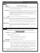
1.0 — General Information and Installation 1.1 INTRODUCTION 1.4 EQUIPMENT SUPPLIED The Alto-Shaam® Quickchiller is a processing refrigeration system designed to rapidly and uniformly cool hot foods through the "chilling danger zone" of 140° to 40°F (60° to 4°C) in two hours or less. Fast cooling minimizes microbial activity, thereby controlling quality and sanitation in prepared foods. As a result, a five-day storage life is achieved. The Quickchiller is shipped from the factory fully assembled.
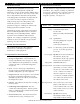
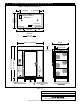
1.0 — General Information and Installation SELF-CONTAINED WATER COOLED CONFIGURATION 38-1/2" (978mm) 35-1/2" (902mm) 24" (610mm) SELF-CONTAINED COMPRESSOR CONFIGURATION 27-1/2" (699mm) 18" (457mm) 17" (432mm) 18" (457mm) OPENING TOP VIEW 38-1/2" (978mm) ® ™ QUICK CHILL ................... A HOLD FOOD ..................... B DEFROST FOOD ............... C PRINT REPORT................. D — 0 CE CHILLING or HOLDING 1 . L O A D F O O D.
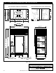
1.0 — General Information and Installation REMOTE COMPRESSOR CONFIGURATION 9" (229mm) 9" (229mm) 35-1/2" (902mm) Field Connections Enclosure ELECTRICAL CONNECTION 18" (457mm) 27-1/2" (699mm) 18" (457mm) OPENING TOP VIEW 38-1/2" (978mm) 63-1/2" (1613mm) ELECTRICAL CONNECTION ® ™ QUICK CHILL ................... A HOLD FOOD ..................... B DEFROST FOOD ............... C PRINT REPORT................. D — 0 CE CHILLING or HOLDING 1 . L O A D F O O D.
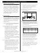
1.0 — General Information and Installation 1.5 RECEIPT AND UNPACKING 1.6.3 DOOR SEAL: Check the door gasket to make certain it is sealing properly and that the gasket provides an even and positive seal around the entire door frame. AAA AA A AAA FIG. 1.6.4 PLUMBING: MODEL QC-100 Note: In certain instances, it may be necessary to remove doors and door hardware to negotiate tight spaces.
1.0 — General Information and Installation 1.6.6 ELECTRICAL: The Quickchiller must be installed by a qualified electrician. This appliance must be branch circuit protected with proper ampacities in accordance with the wiring diagram located in this manual. In the U.S.A., the chiller must be properly grounded in accordance with the National Electrical Code and applicable local codes. 1.6.7 All electrical connections have been made and tested by the factory.
2.0 — Control Set-Up and Operation 2.1 START-UP PROCEDURES 2.1.1 Place the branch circuit breaker (main panel) in the ON position. Then place the Quickchiller circuit breaker in the ON position. button pressed ONCE. Relock the control panel and enter the correct password to gain access to the User Setting Menu screen. 2.1.2 The Main Menu screen must appear on the Control display (see figure 2.1.3). If the Main Menu screen appears, skip Sections 2.1.3 thru 2.1.5 and proceed with SET-UP per Section 2.2.
2.0 — Control Set-Up and Operation MICROPROCESSOR CONTROL ® ™ QUICK CHILL ................... HOLD FOOD ..................... DEFROST FOOD ............... PRINT REPORT................. — 0 CE A B C D The Alto-Shaam ® Quickchiller ™ includes a microprocessor control panel which utilizes a menu screen to guide the operator through all operation mode sequences. MENU SCREEN — MAIN MENU SHOWN A B C D CONTROL KEYBOARD CHILLING or HOLDING 1. LOAD FOOD.
2.0 — Control Set-Up and Operation CONTROL MODE OVERVIEW Ta bl e 2.4.1 Mode Operation Description Auto Chill Refrigeration is controlled only by the food probe(s). Refrigeration continues until all food probes achieve chill setpoint temperature, whereupon the control automatically enters HOLD Mode. Timed Chill Refrigeration is controlled by chill time entered and the cabinet air sensor. While chilling, the cabinet air temperature may become excessively cold prior to chill time expiration.
2.0 — Control Set-Up and Operation 2.5 MAIN MENU The main menu is the starting point for all functions of the Quickchiller. This includes starting the hold, defrost, and chill cycles; report printing; and changing the system configuration. HOLD MODE SCREEN There are four main options shown on the main menu screen. These options are selected with control keyboard buttons "A" through "D." The remaining options are initiated by holding down a number button for 5 seconds.
2.0 — Controls, Operation and Start-Up 2.7 SHUT-DOWN PROCEDURE The Quickchiller can be shut-down at the end of the production day whenever any menu screen which includes STOP=D is displayed. Press "C" on the keyboard to continue shutdown. The Main Menu Screen will appear in the display. Before starting unit shut-down, make certain all product has been removed from the unit. Press "D" on the keyboard to begin shut-down. MAIN MENU SCREEN QUICK CHILL . . . . . . . . . . A HOLD FOOD . . . . . . . . . . .
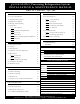
2.0 — Controls, Operation and Start-Up AT- A - G L A N C E QC-100 CONTROL SETTINGS 2.8 HARDWARE NOTES NOTE: Refer to Operation and Procedure Guide, Section 9.0. PRINTER . . . . . . . . . . . . . . . . . . Printer Interface Baud Rate Stop Bits Printing Delay Sample Period, min. Print Grid Spacing Print Grids Printer Columns BUZZERS/TIMEOUTS . . . . . . . Probe Mute Time, sec. Chill Done Time, sec. Are-U-Sure Time, sec. DefrstDone Time, sec.
3.0 — Cleaning & Maintenance 3 . 1 INTRODUCTION To insure trouble free operation and the highest level of sanitation control, periodic cleaning and maintenance is required. The maintenance system should be aimed at maximizing the efficient utilization of maintenance personnel, minimizing down time, and providing the orderly acquisition of spare parts for support. If already established at the location site, perform scheduled maintenance in accordance with the standards in the Maintenance Index Plan.
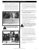
3.0 — Cleaning & Maintenance 3.5 EVAPORATOR CONDENSATE DRAIN HOSE INSPECTION AND CLEANING 3.6 MONTHLY COMPRESSOR AND CONDENSER MAINTENANCE 1. Every 4-6 months, the evaporator coil and condensate drain hose should be inspected for blockage due to spilled food and sauces which can accumulate about the base of the coil and clog the entrance to the drain hose. Keep the condenser coils free of dust and debris to insure proper air circulation and cooling of the refrigeration system. 1.
4.0 — Parts Identification 4 . 1 — Q C - 1 0 0 C O N T R O L & E L E C T R I C A L PA RT S L I S T ITEM DESCRIPTION QUANTITY PART NO. 1. 40A Circuit Breaker (On/Off) 1 Cosp PCCC50 2. Compressor Fuse Blocks-15A ( U P P E R ) 1 FU-3772 — Fuses, 15A, Glass G 2 FU-3775 Compressor Fuse Block-20A (lower) 1 FU-33239 — Fuses, 20A, Class G 2 FU-33042 4. Filter-EMF 1 FI-3580 5. Door Lock 1 LK-23046 3. Keys, Door Lock LK-24176 6. I/O Cable 1 CB-33154 7.
#8401 QC-100 INSTALLATION & MAINTENANCE MANUAL ® MENOMONEE FALLS, WISCONSIN, U.S.A. SCALE: LRL 04/16/01 DATE: DWN BY: QC-100 Quickchiller™ Processing Refrigeration System MODEL: REV: FIG. 4.1 — Control & Electrical Parts List ITEM: PG.
4.0 — Parts Identification 4 . 3 — Q C - 1 0 0 - R E F R I G E R AT I O N PA R T S L I S T ITEM 1. DESCRIPTION QUANTITY PART. NO. Condensing Unit (self contained) 2 Cosp RWC720 Condensing Unit (water cooled) 2 Cosp RUX190 2. Filter Dryer 2 Cosp RWFD03 3. Sight Glass 2 Cosp RWSG02 4. Solenoid Valve 2 Cosp RWSV04 5. Solenoid Coil 2 Cosp RWSC02 6. Evaporator Coil 6 Cosp RWE221 7. Evaporator Fan Motor 12 Cosp LWEM16 8. Expansion Valve (1/2 ton) 6 Cosp RWEV30 9.
5.0 — Diagnostic and Repair Procedure 5.1 INTRODUCTION 5.2.1 SOLENOID CHECK: The relays, which control the compressors, fans, solenoids, and heaters, can be individually controlled by the microprocessor control set in a manual mode. The following test will verify that these components are being controlled and will verify the operational integrity of the relays and fuse sets. Press button 1 and button 2 on the numeric keyboard several times.
5.0 — Diagnostic and Repair Procedure 5.3 CONDENSING UNITS The condensing units operate only when the system is in a cooling mode and the food storage compartment requires a decrease in temperature. If it appears the condensing units are not functioning properly and the General Diagnostic Procedure (4.2.4) on the preceding page was unable to pinpoint the specific cause, the following steps should be taken for further diagnosis. Disconnect main incoming A.C. power to the unit.
6 . 0 — R E F R I G E R AT I O N — Tr o u b l e s h o o t i n g This chart is provided for the assistance of refrigeration technicians only and is not intended for use by untrained or unauthorized service personnel. If your Alto-Shaam Quickchiller is not operating properly, check the following BEFORE calling your Authorized Alto-Shaam Service Agent: ➾ Check the power flow to the unit. Fuses OK? Breakers OK? DO NOT ATTEMPT TO REPAIR OR SERVICE THE QUICKCHILLER BEYOND THIS POINT.
6.0 — CONTROL — Troubleshooting PROBLEM POSSIBLE CAUSE Alphanumeric display is blank. If power is connected to the unit and the main circuit breaker is on, the display on the control should be illuminated with a green tinged background. Control needs to be reset. Unresponsive control. If the control does not respond to operator key presses or the screen on the display appears frozen or sluggish. Control needs to be reset. Power failure threshold is set too low. Control board is faulty.
DOOR SWITCH I/O CABLE LEFT HAND FANS L1 L1 3-4 1-2 5-6 3-4 HEATERS HEATERS 1-2 L1 1 2 3 L1 4 SOLINOID 5 6 RH L1 COMPRESSOR LH NC L1 RELAY ACCESSORY FUSES 5-6 GND +5V +5 VDC CPU POWER RIGHT HAND FANS POWER IN 24 VAC INDICATOR LIGHTS I/O PORT ITEM: Relay Board MODEL: Quickchiller Processing Refrigeration System DATE: 04/04/97 ® MENOMONEE FALLS, WISCONSIN 53051, U.S.A. #8401 QC-100 INSTALLATION & MAINTENANCE MANUAL PG.
PG.
#8401 QC-100 INSTALLATION & MAINTENANCE MANUAL PG.
PG.
#8401 QC-100 INSTALLATION & MAINTENANCE MANUAL PG.
PG.
TRANS P O RTAT I O N DAMAGE and CLAIMS LIMITED WARRANTY All Alto-Shaam equipment is sold F.O.B. shipping point, and when accepted by the carrier, such shipments become the property of the consignee. Should damage occur in shipment, it is a matter between the carrier and the consignee. In such cases, the carrier is assumed to be responsible for the safe delivery of the merchandise, unless negligence can be established on the part of the shipper. 1.