User's Manual LTODRIVE3.4 3 WAY STEREO DIGITAL X OVER www.altoproaudio.com Version 2.
Fuse SAFETY RELATED SYMBOLS To prevent fire and damage to the product, use only the recommended fuse type as indicated in this manual. Do not short-circuit the fuse holder. Before replacing the fuse, make sure that the product is OFF and disconnected from the AC outlet. CAUTION RISK OF ELECTRIC SHOCK DO NOT OPEN This symbol, wherever used, alerts you to the presence of un-insulated and dangerous voltages within the product enclosure.
PREFACE Dear Customer: Thanks for choosing researches. For our LTO DRIVE3.4 and thanks for choosing one of the results of LTO AUDIO TEAM job and LTO AUDIO TEAM , music and sound are more than a job... are first of all passion and let Us say our obsession! We have been designing professional audio products for a long time in cooperation with some of the major brands in the world in the audio field.
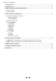
TABLE OF CONTENTS 1. INTRODUCTION ....................................................................................................................................4 2. FEATURE LIST ......................................................................................................................................4 3. FRONT AND BACK PANELS DESCRIPTION........................................................................................4 3.1 The Front Panel 3.2 The Rear Panel 4.
1. INTRODUCTION Thank you very much for expressing your confidence in LTO products by purchasing our LTO DRIVE3.4. With the LTO DRIVE3.4 you have acquired an extremely musical and flexible Active Crossover which will provide you also the subwoofer application. Our new LTO DRIVE 3.
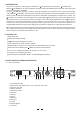
Power SW with LED (1) Turns the apparatus on and off. Press this SW, the power LED inside the SW will turn on. Dial Control knob (5) Used to change editable values. 3.2.
4.2 Operational Overview At system startup the following splash screens will be shown on the graphic display. ALTO DRIVE3.4 Version1.0 Wait Init System The LTO DRIVE3.4 is booting and initializing its hardware and software, loading the last used preset and the user interface. The process lasts a few seconds, afterwards the system goes to the Utility Menu (Utility Led is ON). 4.2.1 UTILITY MENU The Utility menu is accessed by means of the Utility key (Utility Led is ON).
To save a preset it is necessary to select the Preset item; using the dial it is possible to choose the desired preset number, to be confirmed pressing the Enter key. After data saving, a character string (preset name) will be shown to the user for editing (max 8 chars).
1 2 3 4 5 6 LIMITER PRESET 01 2/2 e. Password With this function the user can decide if the device has to be protected from unauthorized tampering: PASSWORD 000000 NEW PASSWORD PRESET 01 1/1 With the Up/Down key it's possible to select the Password, New Password and page number items; selection is highlighted printing the item in reverse color. PASSWORD 000000 NEW PASSWORD PRESET 01 1/1 To have complete access to the system, the fields PASSWORD and NEW PASSWORD must match.
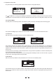
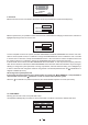
a. Routing This function allows to configure the signal input/output path: 1/1 indicates the number of page; when it's selected it is possible to get back to the main menu pressing the Esc key. ROUTING 1 2 3 4 5 6 L IN R PRESET 01 O U T 1/1 With the Up/Down keys it is possible to select the inputs and the outputs sequentially. In the pictures below the selection sequence is shown.
This graphic screen shows the frequency response of the channel. Use Up/Down/Left/Right keys to select one of the five fields: Page Number, Filter Number, Gain, Frequency, Bandwidth. The selected value can be changed by means of the dial. The selected filter's frequency will be shown by a vertical segment on the display (see above). When a filter parameter is modified, the audio signal is processed real-time, while the picture on the display waits briefly to update.
This graphic screen shows the frequency response of the channel. Use Up/Down/Left/Right keys to select one of the five fields: Page Number, Filter Number, Gain, Frequency, Bandwidth. The selected value can be changed by means of the dial. The selected filter's frequency will be shown by a vertical segment on the display (see above). When a filter parameter is modified, the audio signal is processed real-time, while the picture on the display waits briefly to update.
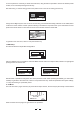
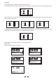
POL. DIR THR. 00 dB REL. 0.4 S ATK. 0.05 S PRESET 01 O1 4/4 POL. DIR THR. 00 dB REL. 0.4 S ATK. 0.05 S PRESET 01 O1 4/4 POL. DIR THR. 00 dB REL. 0.4 S ATK. 0.05 S PRESET 01 O1 4/4 POL. DIR THR. 00 dB REL. 0.4 S ATK. 0.05 S PRESET 01 O1 4/4 POL. DIR THR. 00 dB REL. 0.4 S ATK. 0.05 S PRESET 01 O1 4/4 Use Up/Down/Left/Right keys to select one of the five fields: Page Number, Polarity, Limiter Threshold, Limiter Release, Limiter Attack; the selected values can be changed by means of the dial.
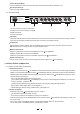
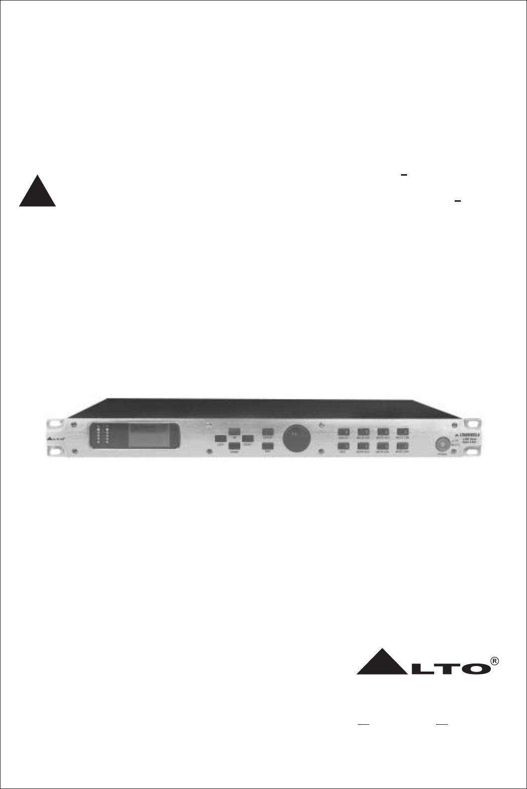
LOW AMP PROFESSIONAL HIGH POWER STEREO AMPLIFIER PROT CLIP SIG CLIP SIG ON R LTO OFF POWER CH-A CH-B MID AMP PROFESSIONAL HIGH POWER STEREO AMPLIFIER PROT CLIP SIG CLIP SIG ON R LTO OFF POWER CH-A CH-B HIGH AMP PROFESSIONAL HIGH POWER STEREO AMPLIFIER PROT SIG CLIP CLIP SIG ON R LTO OFF CH-A POWER PUSH CH-B PUSH MIDI AC INPUT 95-240V~60-50Hz Rated Power Consumption 15W FUSE: NEW MODEL 210-240V: T250mAL 250VAC 95-120V: 500mA 250VAC REPLACE FUSE WITH CORRECT TYPE ONLY T
6. APPENDIX LTO DRIVE3.4 Midi standard control PROGRAM CHANGE Parameter Value Legend 0 Preset Factory Preset 01 Preset 02 to preset 64 1, 2, 3,......, 64 Preset User CONTROL CHANGE Parameter Controller Value 0 0, 1, 2 Mode Channel 22 0, 1 Mode Channel 22 Output Volume 7 0,..., 48 High Pass Filter 17 0,...
3. After MIDI use of ALTO DRIVE3.4 it's advisable to run a manual STORE to save preset changes done by means of the external controller. After saving, reboot the ALTO DRIVE3.4 to use it as a stand-along unit. 4. When setting and resetting mutes (controller 23) by MIDI, the relative LEDs are NOT actived. MIDI Controllers Values Amplitude d\u 0 1 2 15dB / 15dB step 0.5dB (Value = d u) 3 4 5 6 7 8 9 0 15.0dB 14.5dB 14.0dB 13.5dB 13.0dB 12.5dB 12.0dB 11.5dB 11.0dB 10.5dB 10 10.0dB 09.
7. TECHNICAL SPECIFICATIONS Input Channel Digital Input Gain /+ 12 dB / step 0.5 dB Gain /+ 15 dB / step 0.5 dB Freq 20 Hz 20 KHz step 1/12 oct BandWidth 0.05 oct 3 oct / step 0.05 oct Up to 512 ms minimum step 21us 4 Parametric Filters Delay line Output Channel Digital Out Volume Delay line /+ 12 dB / step 0.5 dB Up to 512 ms minimum step 21us Gain /+ 15 dB / step 0.5dB 5 Parametric Filters Freq 20 Hz - 20 KHz / step 1/12 oct BandWidth 0.05 oct - 3 oct step 0.
Power Supply Connector type Type 3 poles DIN (female) Servo controlled, Switching fuse AC Input 210 240V: T250mAL 250VAC 95 120V: 500mAL 250VAC 95 240V~60 50Hz rated power consumption 15W Graphic display Keyboard Vu meter 128 64 dots 14 user keys/ 8LEDs 2 6 LEDs Size Standard 19"rack Mounting Dimensions weight 483(W) 232.5(D) 3.5Kg(7.72lb) User Interface Physical 17 44(H)mm(19" 9.3" 1.
8. WARRANTY 1. WARRANTY REGISTRATION CARD To obtain Warranty Service, the buyer should first fill out and return the enclosed Warranty Registration Card within 10 days of the Purchase Date. All the information presented in this Warranty Registration Card gives the manufacturer a better under-standing of the sales status, so as to purport a more effective and efficient after-sales warranty service.
SEIKAKU TECHNICAL GROUP LIMITED No. 1, Lane 17, Sec. 2, Han Shi West Road, Taichung 40151 Taiwan http://www.altoproaudio.com Tel: 886-4-22313737 email: alto@altoproaudio.com Fax: 886-4-22346757 All rights reserved to ALTO. All features and content might be changed without prior notice. Any photocopy, translation, or reproduction of part of this manual without written permission is forbidden. Copyright c 2005 SEIKAKU GROUP NF 01201-2.