User's Manual AMX-180/ AMX-180FX 18-CHANNEL MIXING CONSOLE/ WITH DIGITAL EFFECTS R LTO www.altoproaudio.com Version 1.
the recommended fuse type as indicated in this manual. Do not short-circuit the fuse holder. Before replacing the fuse, make sure that the product is OFF and disconnected from the AC outlet. SAFETY RELATED SYMBOLS CAUTION RISK OF ELECTRIC SHOCK DO NOT OPEN Protective Ground Before turning the product ON, make sure that it is connected to Ground. This is to prevent the risk of electric shock.
PREFACE Dear Customer: Thank you for choosing the LTO AMX-180 18-Channel Mixing Console (AMX-180FX 18-Channel Mixing Console with Digital Effects), which is the result of our LTO AUDIO TEAM's endeavours. For the LTO AUDIO TEAM, music and audio are more than a profession, it is a passion and an obsession! We have, in fact, been designing professional audio products for a number of years in cooperation with many of the world's major brands.
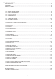
TABLE OF CONTENTS 1.INTRODUCTION...................................................................................................................................................4 2.FEATURES...........................................................................................................................................................5 3.READY TO START?...............................................................................................................................................6 4.
1. INTRODUCTION Thank you very much for expressing your confidence in LTO products by purchasing LTO AMX-180/AMX-180FX mixing console. The AMX-180/AMX-180FX is a professional compact mixer. You will get the smooth, accurate more natural and open sound from this apparatus, and it is really ideal for gigs, recording and fixed PA installations.
2. FEATURES The AMX-180/AMX-180FX mixing console is designed for professional application.
3. READY TO START? 3.1 Please check the AC voltage available in your country before connecting your AMX-180/AMX-180FX to the AC socket. 3.2 Be sure that the main power switch is turned off before connecting the mixer to the AC socket. Also, you should make sure that all input and output controls are turned down. This will avoid damage to your speakers and avoid excessive noise. 3.
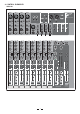
4. CONTROL ELEMENTS AMX-180 MIC 2 MIC 1 MIC 3 MIC 4 2-TRACK IN/OUT STEREO AUX RETURNS 1 L J.T. 2 J.T. 1 2 3 J.T. 1 2 3 MAIN MIX OUTPUT(BAL/UNBAL) J.T. 1 2 3 1 LEFT(MONO) MAIN OUTPUT LEVEL LEFT LEFT BAL OR UNBAL BAL OR UNBAL BAL OR UNBAL BAL OR UNBAL LINE IN 1 LINE IN 2 LINE IN 3 LINE IN 4 TAPE IN INSERT RIGHT RIGHT LINE IN 7/8 LINE IN 9/10 LINE IN 11/12 AUX SENDS CTRL ROOM OUTPUT ALT OUTPUT LEFT(3) L J.T.
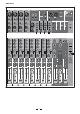
AMX-180FX MIC 2 MIC 1 MIC 3 MIC 4 2-TRACK IN/OUT STEREO AUX RETURNS 1 L J.T. J.T. 2 1 J.T. 2 3 1 1 2 3 1 LEFT(MONO) MAIN OUTPUT LEVEL LEFT LEFT BAL OR UNBAL BAL OR UNBAL BAL OR UNBAL BAL OR UNBAL LINE IN 1 LINE IN 2 LINE IN 3 LINE IN 4 TAPE IN INSERT WITH DIGITAL EFFECTS RIGHT RIGHT LINE IN 7/8 LINE IN 9/10 LINE IN 11/12 AUX SENDS CTRL ROOM OUTPUT ALT OUTPUT LEFT(3) L J.T.
4.1 MONO MIC/LINE CHANNELS 1 These are channel 1 through channel 4. You can connect balanced, low impedance microphones or a low level signal to the XLR socket. On the 1/4" line jack you can connect either a microphone or a line level instrument such as synthesizers, drum machines, effect processors or any other line level signal. Note: You shall never connect an unbalanced microphone to the XLR socket if you do not want to damage both the microphone and mixer.
4.7 3-BAND EQUALIZER A 3-band equalizer is provided for each input channel with a wide range of frequency adjustment. 7 EQ This is the treble control. You can use it to get rid of high frequency noises or to boost the sound of cymbals or the high harmonics of the human voice. The gain range goes from -15dB to +15dB with a center frequency of 12kHz. -15 8 -12 This is the midrange control. It can affect most fundamental frequencies of all musical instruments and human voice.
4.12 PEAK LED 14 Inside your AMX-180/AMX-180FX the audio signal is monitored in several different stages and then sent to the PEAK LED, when this LED blinks, it warns you that you are reaching signal saturation and possible distortion. The PEAK LED will blink with a level that is 6dB before actual clipping. 4.13 FADER 15 This control will adjust the overall level of this channel and set the amount of signal sent to the main output.
4.19 CTRL ROOM OUTPUT 21 These 1/4" sockets are used to send the control room signal to the studio monitor speakers or a second set of PA. 22 4.20 ALT OUTPUT These 1/4" sockets are unbalanced outputs, the signal level to the ALT OUTPUT is adjusted by ALT 3-4 rotary on the front panel. 4.21 PHONES 23 This socket will send out the mix signal to a pair of headphones. 24 4.
4.30 POWER LED 32 This LED indicates when the power is on in your AMX-180/AMX-180FX. 4.31 SOLO MODE SWITCH 33 This button provides two modes: up for PFL (Pre-Fader-Listen) mode, down for AFL (After-Fader-Listen) mode. Engage the button, the output signal of soloed channel will follow the TRIM, EQ, FADER and PAN/BAL control, and the SOLO ACTIVE LED illuminates. Release the button to enter into PFL mode, the output signal of soloed channel is unaffected by the PAN/BAL and FADER control. 4.
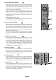
4.38 REAR PANEL DESCRIPTION ON CAUTION MODEL RISK OF ELECTRIC SHOCK DO NOT OPEN 18VAC~ OFF POWER WARNING: SHOCK HAZARD - DO NOT OPEN AVIS: RISQUE DE CHOC ELECTRIQUE - NE PAS OUVRIR SERIAL PHANTOM RATED POWER CONSUMPTION: 25W 43 44 45 - POWER ON/OFF SWITCH 43 This switch is used to turn the main power ON and OFF. - PHANTOM ON/OFF SWITCH 44 This switch will apply +48 Volt Phantom Power only to the 5 XLR MIC inputs. Never connect microphones when the phantom power is on already.
5. INSTALLATION AND CONNECTION Ok, you have got to this point and you are now in the position to successfully operate your AMX-180/AMX-180FX. However, we advise you to read carefully the following section to be the real master of your own mixer. Not paying enough attention to the input signal level, to the routing of the signal and the assignment of the signal will result in unwanted distortion, a corrupted signal or no sound at all.
5.1 Audio Connection Both XLR and 1/4 " TRS connectors are available on the unit. In this way you can interface the unit in several different ways without experiencing any noise or signal loss. You can use the unit with single instruments using The mixer's main insert or on "in-line" between a mixing console's output and a power amplifier.
- Insert Points Connection If you are connecting to a mixing console's main inserts, you may have a single TRS jack for Send and Return, in this case, use an insert "Y" cable that configured like the examples below.
6. FOR THE EXPERTS WHO WANT TO KNOW MORE As we have told you previously in this manual, the AUX SEND2 control both on mono and on stereo channels is factory wired as POST-FADER. If you have some skill in electronic components soldering you can modify this setting and have all your AUX SENDS configured as PRE-FADER.
7. PRESET LIST (For AMX-180FX Model) No. Preset Description Controllable parameter Parameter Variable range 1 VOCAL 1 Simulate a room with small delay time. Decay time Pre-delay 0.8~1.1s 0~79ms 2 VOCAL 2 Simulate a small space with slight decay time. Decay time Pre-delay 0.8~2.5s 0~79ms 3 LARGE HALL Simulate a large acoustic space of the sound. Decay time Pre-delay 3.6~5.4s 23~55ms 4 SMALL HALL Simulate a small acoustic space of the sound. Decay time Pre-delay 1.0~2.
20 A B C MIC5 IN 2 3 1 5e S T R RN TN 3c 4d 2b 1a R RN TN 3c R 4d RN 2b TN 1a T 1 PRESETS 5e S 3c R 4d RN 2b TN 1a T DSP FOOTSWITCH MUTE VARIATIONS RIGHT LEFT 5e S STEREO AUX RETURN 2 RIGHT 5e S LEFT(MONO) 3c R 4d RN 2b TN 1a T 5e S T STEREO AUX RETURN 1 PHANTOM POWER +48V RIGHT LEFT(MONO) 3c 4d 2b 1a 5e S 3c R 4d RN 2b TN 1a T T LO MID HI + 2 DSP BOARD + - + - + - + - 80 2.5K 12K EQ +/-15db - 80 2.
9. TECHNICAL SPECIFICATION Mono input channels Stereo input channels Impedance Equalization Main Mix Section Power supply (AC/AC Adaptor) Microphone input Frequency response Distortion (THD&N) Gain range SNR (Signal Noise Rated) Line input Frequency response Distortion (THD&N) Sensitivity range Line input Frequency response Distortion (THD&N) Microphone input Channel insert return All other inputs Tape out All other output Hi shelving Mid bell Low shelving 10Hz to 55KHz, 3dB 0.
10. WARRANTY 10.1 WARRANTY REGISTRATION CARD To obtain Warranty Service, the buyer should first fill out and return the enclosed Warranty Registration Card within10 days of the Purchase Date. All the information presented in this Warranty Registration Card gives the manufacturer a better understanding of the sales status, so as to purport a more effective and efficient after-sales warranty service.
SEIKAKU TECHNICAL GROUP LIMITED No. 1, Lane 17, Sec. 2, Han Shi West Road, Taichung 40151, Taiwan http://www.altoproaudio.com Tel: 886-4-22313737 email: alto@altoproaudio.com Fax: 886-4-22346757 All rights reserved to ALTO. All features and content might be changed without prior notice. Any photocopy, translation, or reproduction of part of this manual without written permission is forbidden. Copyright c 2005 SEIKAKU GROUP NF01882-1.