R LTO OWNER'S MANUAL A1000.4 DRAGONFLY HIGH EFFICIENCY DIGITAL AMPLIFIER www.altoproaudio.com Version 1.2 OCT.
IMPORTANT SAFETY INSTRUCTION CAUTION RISK OF ELECTRIC SHOCK DO NOT OPEN TO REDUCE THE RISK OF ELECTRIC SHOCK PLEASE DO NOT REMOVE THE COVER OR THE BACK PANEL OF THIS EQUIPMENT. THERE ARE NO PARTS NEEDED BY USER INSIDE THE EQUIPMENT. FOR SERVICE, PLEASE CONTACT QUALIFIED SERVICE CENTERS. WARNING To reduce the risk of electric shock and fire, do not expose this equipment to moisture or rain. Dispose of this product should not be placed in municipal waste and should be separate collection. 11.
IN THIS MANUAL: 1. 2. 3. 4. 5. 6. INTRODUCTION..............................................................................1 FEATURES.....................................................................................1 CONTROL ELEMENTS...................................................................4 OPERATION...................................................................................6 TECHNICAL SPECIFICATIONS.........................................................8 WARRANTY....................
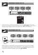
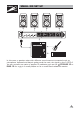
HOOK RECORDING STUDIO SET UP UP R LTO A1000.4 DRAGONFLY ON 24 CLIP 26 20 18 22 24 CLIP 16 26 12 LIMIT 28 dB SIG 20 18 22 24 CLIP 16 26 12 LIMIT 6 30 CH2 - dB 30 6 SIG 20 22 24 CLIP 16 26 12 LIMIT 28 8 - 8 6 CH1 CH3 - LIMIT 28 dB 30 6 SIG CH4 - 28 8 18 22 12 OFF 8 20 18 16 POWER ON dB 30 SIG POWER Also in this case, A1000.4 is connected to the CTRL ROOM output of the mixer and drives four passive studio monitors such as the LTO MICRO4.
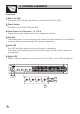
HOOK SMALL GIG SET UP UP R LTO A1000.4 DRAGONFLY ON 18 22 24 CLIP 26 20 18 22 24 CLIP 16 26 12 LIMIT 28 dB 30 20 18 22 24 CLIP 16 26 12 LIMIT 6 SIG CH2 - 28 8 - 8 6 CH1 dB 30 20 22 24 CLIP 16 26 12 LIMIT 6 SIG CH3 - 28 dB 30 LIMIT 6 SIG CH4 - 28 8 20 12 OFF 8 18 16 POWER ON dB 30 SIG POWER In this case, a passive mixer with different sound sources connected such as microphone, keyboard and electric guitar send the main mix signal to the A1000.4.
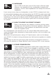
SP OT L IG 3. CONTROL ELEMENTS HT Front Panel: 1 Power On LED This green LED will light up when you switch the A1000.4 ON. 2 Power Switch To switch the A1000.4 ON and OFF. 3 Level Control for Channels 1, 2, 3 & 4 Adjust the output signal level of the respective channel. 4 Clip LED It will flash when you are reaching the maximum power output of the amplifier. It should flash only occasionally for optimum operation. 5 Limit LED This LED will flash when the internal limiter is operating.
SP OT L IG 3. CONTROL ELEMENTS HT Rear Panel: 7 Input sockets These sockets accept the balanced signal from XLR and 1/4" connectors as well. These Inputs are compatible with low-impedance, unbalanced/balanced, line-level outputs emanating from such as mixers, synthesizers, drum machines, direct boxes, crossovers, etc. Electric guitars, microphones, and other low level/high-impedance output devices require a pre-amp or a D/I box. The input circuits of your A1000.4 are electronically balanced.
A DEEPER LOOK: BALANCED OR UNBALANCED? When cables are very long (e.g., over 6 meters/20 feet), the cable itself can act as an "antenna" and pick up radio frequency noise, AC hum, or other types of noises. To avoid these problems, many recording studios and live sound installers use balanced lines. The average application may not require balanced lines, but committing balanced connectors between the mixer and your A1000.4 will cause less ground loops and hum in the system.
4.2 IMPEDANCE Your A1000.4 will easily drive 4 Ohm loads in Stereo mode. However, the impedance of any loudspeaker changes with frequency, and its rated impedance is not always its minimum impedance. If you connect more than one loudspeaker to the A1000.4, please check that the actual load impedance does not drop below the A1000.4's rated output load that is 4 Ohm. Your A1000.
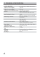
5. TECHNICAL SPECIFICATIONS A1000.4 DRAGONFLY 20 Hz 20 kHz@ 0.
6. WARRANTY 1. WARRANTY REGISTRATION CARD To obtain Warranty Service, the buyer should first fill out and return the enclosed Warranty Registration Card within 10 days of the Purchase Date. All the information presented in this Warranty Registration Card gives the manufacturer a better understanding of the sales status, so as to provide a more effective and efficient after-sales warranty service.
SEIKAKU TECHNICAL GROUP LIMITED NO. 1, Lane 17, Sec. 2, Han Shi West Road, Taichung 40151, Taiwan http://www.altoproaudio.com Tel: 886-4-22313737 email: alto@altoproaudio.com Fax: 886-4-22346757 All rights reserved to ALTO. All features and content might be changed without prior notice. Any photocopy, translation, or reproduction of part of this manual without written permission is forbidden. Copyright c 2007 Seikaku Group NF02215-1.