
Owner`s manual


4
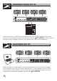
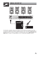
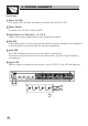
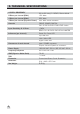
3. CONTROL ELEMENTS
It will flash when you are reaching the maximum power output of the amplifier.
It should flash only occasionally for optimum operation.
Front Panel:
1 Power On LED
This green LED will light up when you switch the A1000.4 ON.
2 Power Switch
To switch the A1000.4 ON and OFF.
3 Level Control for Channels 1, 2,3&4
Adjust the output signal level of the respective channel.
4 Clip LED
5 Limit LED
This LED will flash when the internal limiter is operating.
The limiter will prevent distortion and will protect the life of high frequency
transducers.
6 Signal LED
When a signal is applied to the input of your A1000.4, this LED will light up.
SPOTLIGHT
POWER
ON
OFF
POWER ON
A1000.4
DRAGONFLY
R
LTO
30
12
16
20
18
6
22
24
26
28
dB
8
-
CLIP
SIG
LIMIT
CH1
30
12
16
20
18
6
22
24
26
28
dB
8
-
CLIP
SIG
LIMIT
CH1
30
12
16
20
18
6
22
24
26
28
dB
8
-
CLIP
SIG
LIMIT
CH2
30
12
16
20
18
6
22
24
26
28
dB
8
-
CLIP
SIG
LIMIT
CH3
30
12
16
20
18
6
22
24
26
28
dB
8
-
CLIP
SIG
LIMIT
CH4
1
2
3
4
5
6
30
12
16
20
18
6
22
24
26
28
dB
8
-
CLIP
SIG
LIMIT
CH1
30
12
16
20
18
6
22
24
26
28
dB
8
-
CLIP
SIG
LIMIT
CH1
30
12
16
20
18
6
22
24
26
28
dB
8
-
CLIP
SIG
LIMIT
CH2
30
12
16
20
18
6
22
24
26
28
dB
8
-
CLIP
SIG
LIMIT
CH3
30
12
16
20
18
6
22
24
26
28
dB
8
-
CLIP
SIG
LIMIT
CH4