User's Manual HPA6 6-Channel HEADPHONE AMPLIFIER R LTO www.altoproaudio.com Version 2.
Fuse SAFETY RELATED SYMBOLS To prevent fire and damage to the product, use only the recommended fuse type as indicated in this manual. Do not short-circuit the fuse holder. Before replacing the fuse, make sure that the product is OFF and disconnected from the AC outlet. CAUTION RISK OF ELECTRIC SHOCK DO NOT OPEN This symbol, wherever used, alerts you to the presence of un-insulated and dangerous voltages within the product enclosure.
PREFACE Dear Customer: Thanks for choosing LTO HPA6 6-Channel Headphone Amplifier and thanks for choosing the one of results of LTO AUDIO TEAM job and researches. For our LTO AUDIO TEAM, music and sound are more than a job...are first of all passion and let us say...our obsession! We have been designing professional audio products for a long time in cooperation with some of the major brands in the world in the audio field.
TABLE OF CONTENTS 1. INTRODUCTION .....................................................................................................................................4 2. FEATURE LIST .......................................................................................................................................4 3. CONTROL ELEMENTS ..........................................................................................................................4 3.1 The Front Panel 3.2 The Rear Panel 4.
1. INTRODUCTION Thank you very much for expressing your confidence in LTO products by purchasing our HPA6 6-Channel Headphone Amplifier. With the HPA6 you have acquired an extremely musical and flexible 6-Channel Headphone Amplifier. Featuring six stereo headphone amplifiers, The LTO HPA6 6-Channel Headphone Amplifier performs a number of necessary tasks, not all of which are headphone related.
1. Direct In Input The Direct In Input is used to feed the external program sources into the main signal path, comparing to the Main Input on the rear panel, this input presents the priority character. 2. Input Gain Control This control sets the input signal level coming from Main In. 3. Input Level Meter This meter tells you the level of the main input signal coming from Main/Direct In, and the range goes from -24dBu to +18dBu. 4.
13. Fuse holder / Voltage selector You must be sure of the Voltage available in your Country because this is a Dual Voltage Unit. Voltage operation can be changed through the fuse protecting the power supply but this operation must be performed by a qualified Engineer.
4. INSTALLATION & CONNECTION 4.1 Mains Connection This is a dual voltage unit. Please ensure that the LTO HPA6 6-Channel Headphone Amplifier is set to the correct supply voltage before plugging the power cord into the wall outlet, use the same fuse as marked on the fuse holder at the AC power connection socket. Do not insert power cord into the unit until voltage has been correctly set. Do not plug the power cord into AC power until voltage has been correctly set.
Balanced TIP RING SLEEVE Tip Ring Sleeve SLEEVE RING TIP 3 3 1 1 2 2 1 3 2 TIP RING SLEEVE Tip Ring Sleeve 1 2 1 2 3 3 Tip Ring 1 2 3 Sleeve Unbalanced 1 Tip Ring 3 2 Sleeve TIP RING SLEEVE Tip 1 3 2 Sleeve 1 2 3 1 2 3 1 TIP SLEEVE 2 3 1 2 3 Tip TIP SLEEVE Sleeve SLEEVE TIP Tip Ring TIP RING SLEEVE SLEEVE RING TIP Cent r e Screen Tip Sleeve Tip Ring Sleeve Sleeve Tip Cent r e Sleeve Screen Tip Ring Centre Sleeve Screen TIP SLEEVE TIP RING SLEEVE 2 2 3 3
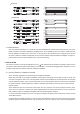
Headphone output2 Headphone output3 Headphone output1 INPUT LEVEL(dBu) 24 18 12 6 0 6 18 24 L 0 2 24 L 0 2 R 24 5 1 3 OUTPUT LEVEL(dBu) 4 12 CLIP MUTE L 0 2 R 24 5 1 Headphone output5 3 OUTPUT LEVEL(dBu) 4 12 CLIP MUTE L 0 2 R 24 5 1 3 OUTPUT LEVEL(dBu) 4 12 CLIP MUTE Headphone output6 L 0 2 R 24 5 1 3 OUTPUT LEVEL(dBu) 4 12 CLIP MUTE L 0 2 4 12 CLIP MUTE R 5 1 4 MAIN IN AUX BALANCED AUX IN DIRECT IN 5 1 R 3 OUTPUT LEVEL(dBu) 4
5.3 The HPA6 in Studio Application Generally, the Aux In Inputs are used to feed a further input signal, which can be mixed with the Main/Direct In signal via Balanced Control, so that, well understood this function, you can get the wonderwork in the studio field.
6. TECHNICAL SPECIFICATIONS AUDIO INPUT MAIN input Connectors XLR and 1/4" jack Type RF filtered, servo balanced input Impedance 50 kOhms balanced, 25 kOhms unbalanced Max.input level +21 dBu balanced and unbalanced (unity gain) CMRR typ.40 dB, >55 dB @ 1kHz AUX IN and DIRECT IN input Connectors Type 1/4" TRS (tip=left, ring=right, sleeve=ground) Impedance 25 kOhms unbalanced Max.
7. WARRANTY 1. WARRANTY REGISTRATION CARD To obtain Warranty Service, the buyer should first fill out and return the enclosed Warranty Registration Card within 10 days of the Purchase Date. All the information presented in this Warranty Registration Card gives the manufacturer a better understanding of the sales status, so as to purport a more effective and efficient after-sales warranty service.
SEIKAKU TECHNICAL GROUP LIMITED No. 1, Lane 17, Sec. 2, Han Shi West Road, Taichung 40151 Taiwan http://www.altoproaudio.com Tel: 886-4-22313737 email: alto@altoproaudio.com Fax: 886-4-22346757 All rights reserved to ALTO. All features and content might be changed without prior notice. Any photocopy, translation, or reproduction of part of this manual without written permission is forbidden. Copyright c 2005 SEIKAKU GROUP NF 00893-2.