
User`s manual

5
SPOTLIGHT
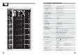
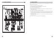
4. CONTROL ELEMENTS
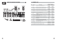
1 MONO MIC/LINE Channels
Your LYNX-MIX244 is equipped with 16 low-noise microphone preamplifier
with optional phantom power, 50 dB of Gain and over 115 dB of S/N ratio.
You can connect almost any type of microphone. Dynamic microphones do
not need phantom power. Use phantom power only with condenser mic but
make sure that the phantom power button is disengaged before connecting
the microphone. Phantom power will not damage your dynamic microphones,
so make sure to read the MIC instructions manual before engaging phantom
power. Use this switch (53) to activate/deactivate phantom power. These
channels are also equipped with 1/4" TRS balanced/unbalanced LINE-IN plugs
to connect line-level instruments such as keyboards, drum machines and
effect devices.
1
These are channels 17 through 24. They are
organised in stereo pair and provided with XLR
sockets (17 & 18 only) and 1/4" TRS phone jacks.
If you connect only the left jack, the input will
operate in mono mode, that is the mono signal
will appear on both input channels. You can use
these inputs with a stereo keyboard, drum
machine, etc.
2 STEREO INPUTS
3
2
This is where you connect external sound
processors such as compressor-limiter,
equalizers, etc.. The insert point is available on
the first 16 MIC channels only.
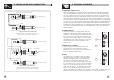
3 MONO Channel INSERT
4 TRIM
The TRIM control is applied in the mono MIC
and stereo input channels. It provides with 2
different indications: One is for the MIC and
the other for LINE levels. When you use a
microphone, you shall read the MIC ring (0~50
for mono MIC input, 0~40 for stereo channels);
when you use a line level instrument, you shall
read the LINE ring (+15~-35 dB for mono MIC
input, +20~ 20 dB for stereo channels). For
optimum operation, you shall set this control in a way that the PEAK LED (15)
blinks only occasionally in order to avoid distortion on the input channel.
-
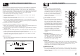
Sleeve=Ground/Screen
Tip=Signal
Sleeve=Ground/Screen
Ring=Return Signal (Connected together)
To Channel Insert
To Tape or FX Input
'Tapped' Connection Direct Output Lead
(Enables the Insert to be used as a Direct Output
while maintaining the channel signal flow)
Sleeve
Sleeve=Ground/Screen
Ring=Return Signal
Tip=Send Signal
To Channel Insert
To Processor Input
To Processor Output
Ring
Tip
Y-Stereo lead for insert Connection
(To be used when the processor does not employ a
single jack connection for the In/Out Connections)
16
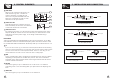
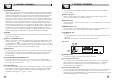
5. INSTALLATION AND CONNECTION
MIC 1
BAL/UNBAL
INSERT
LINE IN 1
(MONO)
LEFT
MIC 17
RIGHT
LINE IN 17
LINE IN 18
BAL/UNBAL