User's Manual MISTRAL900/1500 STEREO POWER AMPLIFIER R LTO www.altoproaudio.com Version 1.
SAFETY RELATED SYMBOLS Never cut off the internal or external protective grounding wire or disconnect the wiring of protective grounding terminal. CAUTION RISK OF ELECTRIC SHOCK DO NOT OPEN Operating Conditions This apparatus shall not be exposed to dripping or splashing and that no objects filled with liquids, such as vases, shall be placed on this apparatus. To reduce the risk of fire or electric shock, do not expose this apparatus to rain or moisture. Do not use this apparatus near water.
Preface Dear Customer: Thanks for choosing LTO MISTRAL1500/900 Stereo Power Amplifier and thanks for choosing one of The results of AUDIO TEAM job and researches. LTO For our LTO AUDIO TEAM, music and sound are more than a job ...are first of all passion and let us say...our obsession! We have been designing professional audio products for a long time in cooperation with some of the major brands in the world in the audio field.
TABLE OF CONTENTS 1. INTRODUCTION.......................................................................................................................................4 2. FEATURES .... .........................................................................................................................................4 3. CONTROL ELEMENTS............................................................................................................................5 3.1 The Front Panel 3.2 The Rear Panel 4.
1. LTO MISTRAL1500/900 The LTO MISTRAL is a line of high power, low profile, professional Power Amplifiers with advanced features and great reliability. They deliver tremendous power in only two rack spaces, providing high level performance under the most demanding conditions. An automatic speed fan matches cooling capacity with heat requirements. The amplifier frame contains all solid-state circuitry, using complementary silicon output devices.
3. CONTROL ELEMENTS 3.1 Front Panel 2 3 1500 ON CH1 CH2 CLIP LIMIT OPERATING/ PROTECTION POWER ON OFF R POWER LTO Stereo Power Amplifier 1 6 4 5 6 1 Power Switch Turn the unit power on or off. 2 Clip Led When the signal distortion reaches or surpasses 0.5%, the Led lights up. This means the output level of signal source is too high and it is time to reduce input level until clip led turning off. 3 Output Limiter Led While the unit is limiting the output signal, the Led lighting up.
Power Source Socket It is used to connect power cord, after setting the proper voltage, connect one end of power cord with the unit and another end with mains. 8 Manual Reset Pushing-Button This switch works as fuse for protecting the unit from damage. When the unit is overloaded or the temperature inside the unit is too high, this pushing-button will spring up and break the power supply. The power supply will be restored with pushing this switch down again.
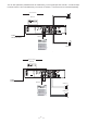
4. APPLICATION Total two optional modes: Please see following diagram for connecting the power amplifier into your audio system. 4.1 Stereo Mode In this mode, Channel 1 and Channel 2 operate independently ( just as traditional stereo amplifier). The signal input into channel 1 can be output from channel 1 only, similarly, the signal input into channel 2 can be output from channel 2 only.
You can also operate the paralleled mode via outside wiring, so, the signal input from channel 1 or 2 will be output from both channel 1 and 2 simultaneously. The volume of channel 1 or channel 2 can be controlled separately.
+ Input Connector Balanced Channel 1 GND 1 3 2 INPUT POWER OUTPUTS TIP/PIN 2 RING/PIN 3 SLEEVE/PIN 1 NEW 2 TIDE 1 CH2 2+ 2POS NEG MODE NEW MODEL 2 TIDE OFF ON 1 BRIDGE 1+ 2+ POS NEG CH1 BREAKER OUTPUT1 CH2 1+ 1POS NEG 1 3 3 2 LIMITER STEREO BRIDGE PARALLEL OUTPUT INPUT CH1 TIP/PIN 2 RING/PIN 3 SLEEVE/PIN 1 Apparaten skall anslutas till jordat uttag nar den ansluts till ett natverk CH1 1+ 1POS NEG 1 3 3 2 BRIDGE MONO CH2 SERIAL PARALLEL OUTPUT CH2 OUTPUT2 MODE Release thi
4.2 Bridge Mode In this mode, the signal input into channel 1 will be output from the bridged end, on other hand, the output level control of channel 2 should be turn down to smallest (turn the volume control at counterclockwise). Only the volume control of channel 1 is used to control the volume of whole system.
5. TECHNICAL SPECIFICATIONS MODEL MISTRAL900 MISTRAL1500 20Hz 20KHz@0.1%THD, Stereo Mode 8 ohms per channel(EIAJ) 190W 300W 4 ohms per channel(EIAJ) 300W 500W 8 ohms, 1KHz, 0.1%THD 600W 1000W Distortion (SMPTE-IM) <0.
6. WARRANTY 1. WARRANTY REGISTRATION CARD To obtain Warranty Service, the buyer should first fill out and return the enclosed Warranty Registration Card within 10 days of the Purchase Date. All the information presented in this Warranty Registration Card gives the manufacturer a better understanding of the sales status, so as to purport a more effective and efficient after-sales warranty service.
SEIKAKU TECHNICAL GROUP LIMITED No. 1, Lane 17, Sec. 2, Han Shi W. Road, Taichung, 401 Taiwan http://www.altomobile.com Tel: 886-4-22313737 email: info@altomobile.com Fax: 886-4-22346757 All rights reserved to ALTO Mobile. Due to continued development in response to customer feedback, product features, specifications and/or internal/external design may be changed without prior notice. No photocopying, translation or reproduction of any part of this user manual is allowed without prior written permission.