User's Manual ALTO Q 5-BAND PARAMETRIC EQUALIZER R LTO www.altoproaudio.com Version 2.1 Dec.
the recommended fuse type as indicated in this manual. Do not short-circuit the fuse holder. Before replacing the fuse, make sure that the product is OFF and disconnected from the AC outlet. SAFETY RELATED SYMBOLS CAUTION RISK OF ELECTRIC SHOCK DO NOT OPEN Protective Ground This symbol, wherever used, alerts you to the presence of un-insulated and dangerous voltages within the product enclosure. These are voltages that may be sufficient to constitute the risk of electric shock or death.
PREFACE Dear Customer: Thanks for choosing LTO-Q 5-Band Parametric Equalizer and thanks for choosing one of the results of AUDIO TEAM job and researches. LTO For our LTO AUDIO TEAM, music and sound are more than a job...are first of all passion and let us say...our obsession! We have been designing professional audio products for a long time in cooperation with some of the major brands in the world in the audio field.
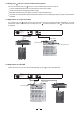
TABLE OF CONTENT 1. INTRODUCTION ....................................................................................................................................4 2. FEATURES ............................................................................................................................................4 3. ELEMENT CONTROLS..........................................................................................................................4 3.1 The Front Panel 3.2 The Rear Panel 4.
1. INTRODUCTION With LTO-Q you have acquired an indispensable toll to add clarity and flexibility to your music. The LTO-Q 5 bands parametric equaliser will provide precise audio signal control to fixed sound installation, live performance and studio applications.
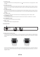
5.The INPUT control You can control the amount of the audio signal fed into your to +15dB. LTO-Q via this control. The range goes from -15dB 6.The HIGH CUT control This control, when activated will cut the high frequencies with a slope of 12dB per octave in a range of 2.5 kHz to 30 kHz. So if you set this control at the maximum position of 30 kHz, the audio signal will pass through without alteration. 7.
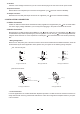
13.AC Inlet After the correct voltage has been set you can connect the AC plug to the unit and in the AC power socket. 14.Input Connectors Both XLR and 1/4" TRS jack input connectors are supplied in your LTO-Q for maximum flexibility. 15.Output Connector Both XLR and 1/4" TRS jack output connectors are supplied in your LTO-Q for maximum flexibility. 4. INSTALLATION & CONNECTION 4.1 Mains Connection A Main AC cable that meets all the international safety regulations is supplied with your LTO-Q.
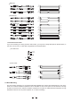
Balanced Tip Ring Sleeve SLEEVE RING TIP TIP RING SLEEVE 3 3 1 1 2 2 1 3 2 TIP RING SLEEVE Tip Ring Sleeve 1 2 1 2 3 3 Tip Ring 1 2 3 Sleeve Unbalanced 1 Tip Ring 3 2 Sleeve TIP RING SLEEVE Tip 1 3 2 Sleeve 1 2 3 1 2 3 1 TIP SLEEVE 2 3 1 2 3 Tip TIP SLEEVE Sleeve SLEEVE TIP Tip Ring TIP RING SLEEVE SLEEVE RING TIP Cent r e Screen Tip Sleeve Tip Ring Sleeve Sleeve Tip Cent r e Sleeve Screen Tip Ring Centre Sleeve Screen TIP SLEEVE TIP RING SLEEVE 3 3 1 1 1
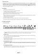
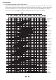
5. APPLICATION 5.1 The Frequency Range of music Instruments Please look at the following table. It gives you an idea of the frequency coverage of the main musical instruments and the human voice. Select a specific instrument and start to "play" with your LTO-Q applying the five bands available on the covered frequencies. Adjust GAIN first and then FREQUENCY and finally Q. See how much control your LTO-Q will give you allowing a perfect contour of your sound.
5.2 Using your LTO-Q in a sound reinforcement system You can successfully use your LTO-Q in a sound reinforcement system in order to: Cut out undesirable frequencies such as tape hiss and/or floor rumble. Create sounds effects enlarging the stereo image. Eliminate feedback using very sharp Q control on selected frequencies. Overboost or overattenuate selected frequencies thanks to the overlapping frequency range of the five bands available. 5.
6. TECHNICAL SPECIFICATIONS AUDIO INPUT Type Active balanced XLR and 1/4" JACK Impedance Balanced: 50kOhm Unbalanced: 25kOhm Operating level +4dBu/ 10dBV Maximum input level Balanced and Unbalanced: +18dBV CMRR >55dB @1kHz Type XLR and 1/4" JACK Impedance Balanced: 60Ohm Unbalanced: 30Ohm Maximum output level +18dBV Bandwidth THD+N% 18Hz to 30kHz at 3dBV 0.02% typ. 1kHz, @+4dBu IMD 0.04% typ. 1kHz, @ 0.
7. WARRANTY 1. WARRANTY REGISTRATION CARD To obtain Warranty Service, the buyer should first fill out and return the enclosed Warranty Registration Card within 10 days of the Purchase Date. All the information presented in this Warranty Registration Card gives the manufacturer a better understanding of the sales status, so as to purport a more effective and efficient after-sales warranty service.
SEIKAKU TECHNICAL GROUP LIMITED No. 1, Lane 17, Sec. 2, Han Shi W. Road, Taichung, 401 Taiwan http://www.altomobile.com Tel: 886-4-22313737 email: info@altomobile.com Fax: 886-4-22346757 All rights reserved to ALTO Mobile. Due to continued development in response to customer feedback, product features, specifications and/or internal/external design may be changed without prior notice. No photocopying, translation or reproduction of any part of this user manual is allowed without prior written permission.