MAXI-Q User's Manual 30+30 BAND DIGITAL EQUALIZER R LTO www.altoproaudio.com Version 1.1 August.
Fuse SAFETY RELATED SYMBOLS To prevent fire and damage to the product, use only the recommended fuse type as indicated in this manual. Do not short-circuit the fuse holder. Before replacing the fuse, make sure that the product is OFF and disconnected from the AC outlet. CAUTION RISK OF ELECTRIC SHOCK DO NOT OPEN This symbol, wherever used, alerts you to the presence of un-insulated and dangerous voltages within the product enclosure.
PREFACE Dear Customer: Thanks for choosing MAXI-Q 30+30 Band Digital Equalizer and thanks for choosing one of the results of AUDIO TEAM job and researches. For our LTO LTO AUDIO TEAM, music and sound are more than a job...are first of all passion and let us say our obsession! We have been designing professional audio products for a long time in cooperation with some of the major brands in the world in the audio field.
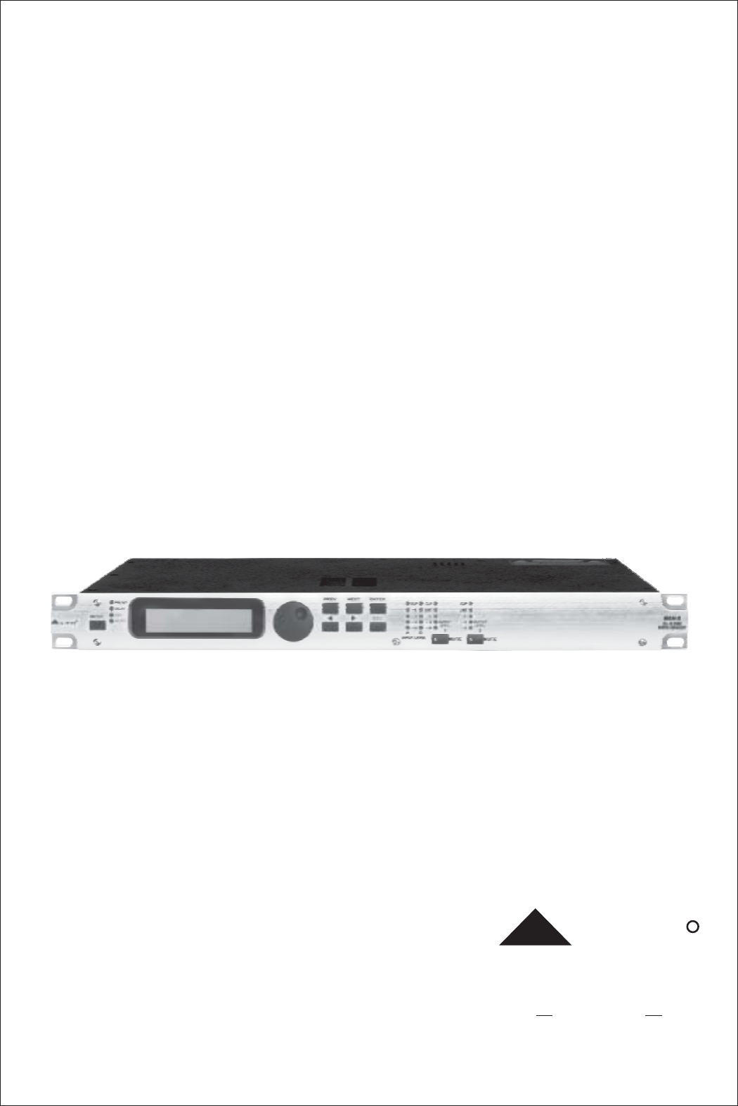
TABLE OF CONTENTS 1. INTRODUCTION .....................................................................................................................................4 2. FEATURES .............................................................................................................................................4 3. CONTROL ELEMENTS .........................................................................................................................4 3.1 The Front Panel 3.2 The Rear Panel 4.
1. INTRODUCTION Your MAXI-Q is a 30+30 Band Digital Equalizer and it also is a powerful versatile signal processor. you can set the input and output configuration only through recalling one of the presets included in the internal memory or PC Editor software. Thanks to the use of selected and expensive components, the MAXI-Q is worth much more than its price. 2.
7.ENTER key The key allows you to access to the selected editing page. Pressing this key, you can edit and confirm the required value of parameter. 8.ESC key The key allows you to exit the selected editing page. It also can be used to reject the value to enter and return to the stored value. 9.Input Level LED Meters The LEDs are used to indicate the level of input A/B.
16.RS 232 This is the serial communication interface port. It allows incoming and outgoing communication between a MAXI-Q and a PC or other MAXI-Q units. You can use the LTO editing software to control functions of all the processor remotely. 17.OUTPUTS These two outputs are balanced XLR connectors. The high quality, low noise, 24 bit converters can make D/A conversion. 18.INPUTS INPUT A and INPUT B are compatible with balanced XLR and JACK. They are audio connectors of the respective sections.
Use the DIAL to find the necessary Factory PRESET (indicated by the letter F). Check that if, among the PRESETS available, there are already some optimised for the specific speaker enclosures being used. Press ENTER. The display shows the PRESET loaded in the units memory and the relative configuration: 2 F A 1 B2 DEBASS (example) 4.2 Memory Initialization 1>To execute the function of "MEMORY INITIATED", keys of "NEXT" and " " must be executed and kept down under turning on.
Press ENTER. The display will show the INA Gain (according to the configuration and other utilities loaded in the memory) I NA GA I N 0 . 0 dB Use the DIAL to change the gain value and watch the level of the signal on the LED ladders until the ideal values are reached. I NA GA I N - 2 . 5 dB Then use the PREV and NEXT keys to access to the INB Gain page (if there is one, this will depend on the configuration and the other utilities loaded in the memory). Repeat the settings as explained above. 4.
4.7 Number of PRESET 2 A 1 B2 F DEBASS 10 Factory Presets and 128 User Presets. 4.8 Type of PRESET 2 F A 1 B2 DEBASS There are 2 categories of PRESETS: F = Factory PRESETS factory programmed, cannot be permanently changed. These include all the system's usable configurations. These are the starting points for Creating User PRESETS from scratch. U = User PRESETS can be programmed by users. 4.9 Name of the PRESET 2 F A 1 B2 DEBASS In the example, the name of preset is DEBASS. 5.
To load a PRESET: Use the DIAL to reach the required Preset. 10 Factory Presets and 128 User Presets. Note: since the system must always be configured, there are no empty memory areas. All User areas unused by custom PRESETS are automatically occupied by the *Default* PRESET, which contains a standard start configuration with all the values of the various parameters at zero. L o a d P r e s e t 2 4 U * De f a u l t * There are 2 distinct categories of PRESETS: Factory-programmed storage.
Press ENTER. The PRESET Naming page appears, by means of which it s possible to edit the name of the PRESET to be saved. The name of the 'start' PRESET (i.e. of the PRESET currently loaded) is proposed as default. The cursor takes up position on the first of the twelve character spaces available. P r e s e t Nam i ng * De f a u l t * At this point: If you decide to accept and confirm the name suggested, press ENTER.
5.2.1 Input Delay Use this menu page to adjust the delay lines of Input A, Input B and SUM. De l a y DELAY The values can be set in the following ranges: I NA DELAY 7 7mS unit range step m 0.0 ~ 900.0 0.5 mm 0 ~ 900000 7 ms 0 ~ 2715 1 us 0 ~ 2715000 21 The measurement unit can be chosen with the function Delay Unit (UTILITY menu - Units submenu). 5.3 Edit menu The values can be set in the following ranges: menu EDIT Input Gain Parameters EQ TYPE Parameters Output Pol.
5.3.1 Input Gain Input gain control. I np u t Ga i n Allows to adjust the amplification of the signal fed in through Inputs A and B. Editing values are in the range +6dB ~ -30dB, with 0.5dB steps. I NA GA I N - 2 . 5 d B Note: Setting the input signal of a digital unit is particularly important, much more than on an analog unit, as any saturation of the A/D converter due to an excessively high input signal causes a typical particularly distinct noise. To achieve a good signal/noise ratio, i.e.
5.3.4 Output Gain Output level control Allows to adjust the signal level of each individual output. Ga i n Ou t p u t Editing values are between +6dB ~ -30dB, with 0.5dB steps. OP1 GA I N - 6 . 5 dB Note: The level of each output is shown by the respective OUTPUT LEVEL LED ladder. To avoid distortion, don't let the red CLIP LED light up. As automatic protection, you can also enable the LIMITER (EDIT menu) on the outputs that require it.
5.3.6 Parameter EQ (PEQ) Input equalizer with 5 parametric filters. Allows to alter the overall tone of the signal connected to the respective input. Also called Master EQ, the equalization of the input signal effects all the outputs connected to the input and the input SUM. The component's characteristic quality and programmability enable it to be used effectively and flexibly.
5.4 UTILITY Menu This menu comprises a series of submenus that allow to set a series of system options and access certain utilities, such as the control of the protection against accidental or unauthorized changes: menu Units UTILITY Delay Unit Temperature Unit Comm.Setup Preset Change RX ID Select Misc. Setup Temperature Output Meters LCD Contrast 5.4.1 UNITS SUBMENU Units Delay Unit Temperature Unit Used this submenu to choose the measurement units to be used with certain functions.
5.4.2 COMM. SETUP SUBMENU Preset Change RX Comm. Setup Preset ID Change Select RX This submenu allows access to the setting of communication with other units via the serial ports. C o mm . S e t u p PRESET Change RX Allows to accept or ignore the PRESET Change command sent via the serial ports from a computer or another MAXI-Q when it loads a PRESET. The settings can be: Ignore PRESET Change commands received. Accept and execute PRESET Change commands.
Use this submenu to set a series of system options. M i s c . S e t u p a. Temperature Used to key in the value of the environmental temperature of place of installation. The system uses this value to automatically compensate for the differentials due to the difference speed of sound Transmission according to the air temperature.
6. CONNECTIONS The following diagrams show the schemes of the recommended cables and some connection examples referred to various system configurations.
7. APPLICATION To operate one or more MAXI-Q units that are connected to a PC, you need to download a free Windows compatible MAXI-Q program from our website. To get a copy, please go to http://www.altoproaudio.com/html/download.php and click "Data Resources/ Downloads" and then "Software Downloads".
8. OPERATION BLOCK DIAGRAM Load Preset PRESET 10 Factory Preset 128 User Preset PREV/NEXT Store Preset DELAY DIAL Delay Input Gain DIAL DIAL DIAL 128 User Preset Parameters -30dB~+6dB Step 0.5dB Gain GEQ01 DIAL -15dB~+15dB Step 0.5dB PREV/NEXT MODE EDIT GEQ30 Gain Output Gain -30dB~+6dB Step 0.5dB Frequency DIAL DIAL DIAL Bandwidth PEQ01 Gain PREV/NEXT Frequency Bandwidth PEQ05 Gain Output Pol. UTILTY DIAL Unit Comm. Setup 21 DIAL DIAL 0.05~3.00OCT 0.
9. TECHNICAL SPECIFICATIONS INPUT section Output Section DSP Section Features General Performance General Connectors Nominal input sensitivity Input Impedance Maximum Input Level Input Gain 2 x COMBO 0 dB (0.775 V) 30kOhm, electronically balanced +20dBu -30 / +6 dB variable in 0.
10. WARRANTY 1. WARRANTY REGISTRATION CARD To obtain Warranty Service, the buyer should first fill out and return the enclosed Warranty Registration Card within 10 days of the Purchase Date. All the information presented in this Warranty Registration Card gives the manufacturer a better understanding of the sales status, so as to purport a more effective and efficient after-sales warranty service.
SEIKAKU TECHNICAL GROUP LIMITED No. 1, Lane 17, Sec. 2, Han Shi West Road, Taichung 40151, Taiwan http://www.altoproaudio.com Tel: 886-4-22313737 email: alto@altoproaudio.com Fax: 886-4-22346757 All rights reserved to ALTO. All features and content might be changed without prior notice. Any photocopy, translation, or reproduction of part of this manual without written permission is forbidden. Copyright c 2005 SEIKAKU GROUP NF 00973 -1.