User's Manual S-12 12-CHANNEL MIXING CONSOLE R LTO www.altoproaudio.com Version 2.
the recommended fuse type as indicated in this manual. Do not short-circuit the fuse holder. Before replacing the fuse, make sure that the product is OFF and disconnected from the AC outlet. SAFETY RELATED SYMBOLS CAUTION RISK OF ELECTRIC SHOCK DO NOT OPEN Protective Ground This symbol, wherever used, alerts you to the presence of un-insulated and dangerous voltages within the product enclosure. These are voltages that may be sufficient to constitute the risk of electric shock or death.
PREFACE Dear Customer: Thank you for choosing the endeavours. For the LTO S-12 12-Channel Mixing Console, which is the result of our LTO AUDIO TEAM's LTO AUDIO TEAM, music and audio is more than a profession, it is a passion and an obsession! We have, in fact, been designing professional audio products for a number of years in cooperation with many of the world's major brands. The LTO line represents unparalleled analogue and digital products made by musicians, for musicians.
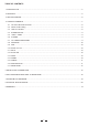
TABLE OF CONTENTS 1.INTRODUCTION........................................................................................................................................................4 2.FEATURES................................................................................................................................................................5 3.GETTING STARTED........................................................................................................................................
1.INTRODUCTION Your S-12 is a 12-channel mixer and it is one of the most popular compact mixing consoles in the world. In fact it has been sold already in terms of thousands of units worldwide. Despite its compact dimensions, great performances and sound quality are insured thanks to the specification of the components used and the building quality.
2. FEATURES The S-12 12-Channel Mixing Console is designed for the professional application, and presents with the following specific features: -. Ultra-low noise 12-channel 2+2-bus mixing console -. 4 MIC input channels with gold plated XLRs and balanced Line inputs -. 4 stereo input channels with balanced TRS jacks -. 2 additional multi-functional stereo AUX Returns -. Ultra-low noise discrete MIC preamps with +48V Phantom power -. Low noise, high headroom -. Peak LEDs on each channel -.
3. GETTING STARTED 3.1 Please check the AC Voltage available in your Country before connecting your S-12 to the AC socket. 3.2 Be sure that the main power switch is turned off before connecting the Mixer to the AC socket. Also, you should make sure that all Input and Output Controls are turned down. This will avoid damages to your speakers and avoid excessive noise. 3.3 Before turning on the S-12 you shall connect it to a power amplifier and turn-on the mixer BEFORE the power amplifier.
4.
1 4.1 The mono MIC/LINE channels These are Channel 1 through Channel 4. You can connect balanced, low impedance microphones to the XLR socket. On the 1/4" phone jack you can connect either a microphone or a line level instrument. You shall never connect an unbalanced microphone to the XLR socket if you do not want to damage both the Microphone and the Mixer. MIC 1 2 1 3 48 Volt phantom power 2 1 It is available only to the XLR Mic sockets.
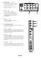
5 4.4 STEREO INPUTS 5 These are Channel 5 through 12. They are organised in stereo pair and they are provided with 1/4" TRS phone sockets. 2 LINE IN 5/6 LINE IN 7/8 LINE IN 9/10 LINE IN 11/12 LEFT(MONO) LEFT (MONO) LEFT (MONO) LEFT (MONO) 1 3 If you connect only the left jack, the input will operate in mono mode. MIC (MONO) TRIM RIGHT 0dB 4.5 +4dBu / -10dBV 60dB MIC RIGHT LEVEL +4dBu -10dBV RIGHT RIGHT LEVEL +4dBu -10dBV LEVEL +4dBu -10dBV 6 7 7 4.
4.8 AUX SEND These two controls will send the audio signal out to Auxiliary busses. AUX 1 can be configured as PRE/POST Fader via the PRE/POST switch: Up for POST Fader, the audio signal will be affected by the main Channel Fader; Down for PRE Fader, the signal is sent out before reaching the main fader. AUX 2 is configured as POST-Fader; However, AUX 2 can also be configure as PRE-Fader through any internal modification. (Please see "MODIFICATIONS" later in this Manual.
4.15 INSERT 18 Insert points are provided for the Mono Mic Channels. When you insert a jack in the insert socket, the signal will be taken out after the Input Gain Control (Trim), sent to an external processor such a compressorlimiter, and returned into the channel strip immediately before the EQ section. Of course, these jacks used must be stereo (Tip Send/Ring Return). CHANNEL INSERT (PRE-FADER/PRE-EQ TIP SEND/RING RETURN) CH4 CH3 CH2 CH1 18 4.16 MAIN SECTION 19 -.
23 24 The both switches are used to determine the master AUX SEND levels. The adjustable range is from - to +15dB. When the effect unit connected to mixer has no input gain control, you can get a further +15dB gain available from these AUX SEND outputs.
28 -. ALT 3-4 This switch is used to adjust the level of the ALT output, and the adjustable range is from - to +15dB. This is another way to offer you an extra independent stereo submix with its own level adjustment knob. -. POWER 29 This LED indicates when the Power is on in your S-12. -. PHANTOM 30 This LED indicates when the Phantom Power is switched on. -.
4.17 REAR PANEL 35 -. AC INLET & FUSE HOLDER Use it to connect your S-12 to the Main AC with the supplied AC cord. Please check the Voltage available in your Country and how the Voltage for your S-12 is configured before attempting to connect your S-12 to the Main AC. 36 2 POWER PHANTOM ON OFF 36 Use only with a 250V fuse -. POWER Apparaten skall anslutas till jordat uttag nar den ansluts till ett natverk This switch is used to turn the Main Power ON and OFF. 35 AC INPUT -.
5. INSTALLATION & CONNECTION Ok, you have got to this point you are now in the position to successfully operate your S-12. However, we advise you to read carefully the following section to be the real Master of your own Mix. Not paying attention enough to the Input signal level, to the routing of the signal and the assignment of the signal will result in unwanted distortion, a corrupted signal or no sound at all.
B. Wiring Configuration You can connect unbalanced equipment to balanced inputs and outputs. Simply follow these schematics.
Ring=Return Signal (Connected together) To Channel Insert Sleeve=Ground/Screen Tip=Signal To Tape or FX Input Sleeve=Ground/Screen 'Tapped' Connection Direct Output Lead (Enables the Insert to be used as a Direct Output while maintaining the channel signal flow) To Processor Input Sleeve=Ground/Screen Tip=Send Signal Tip To Channel Insert Sleeve Ring=Return Signal Ring To Processor Output -Stereo lead for insert Connection (To be used when the processor does not employ a single jack connection
6. FOR THE EXPERTS WHO WANT TO KNOW MORE As we have told you previously in this Manual, the Aux Send 2 Control both on Mono and stereo channels is factory wired as POST-FADER. If you have some skill in electronic components soldering you can modify this setting and have all your AUX sends configured as PRE-FADER.
19 A B C RIGHT PHANTOM POWER +48V MIC5IN 5e S GAIN + - 1 RIGHT LEFT 5e S 3c R 4d RN 2b TN 1a T 5e S 3c R 4d RN 2b TN 1a T STEREO AUX RETURN 2 RIGHT T R RN TN 5e S 3c 4d 2b 1a LEFT(MONO) 5e S 3c R 4d RN 2b TN 1a T MID HI + - + - + - + - SG/OL CHANNEL 5,6 ONLY 2 80 2.5K12K EQ + LO +/-15db 5e S 3c R 4d RN 2b TN 1a T 80 2.
8. TECHNICAL SPECIFICATIONS Mono input channels Microphone input Frequency response electronically balanced, discrete input configuration Distortion (THD&N) Gain range 0.005% at +4dBu, 1kHz 0dB to 60dB(MIC), SNR (Signal Noise Rated) Line input 115dB electronically balanced Frequency response Distortion (THD&N) Sensitivity range 10Hz to 55kHz, +/-3dB 0.005% at +4dBu, 1kHz Line input Frequency response Balanced 10Hz to 55kHz, +/-3dB Distortion (THD&N) 0.005% at +4dBu, 1kHz Microphone input 1.
9. WARRANTY 1. WARRANTY REGISTRATION CARD To obtain Warranty Service, the buyer should first fill out and return the enclosed Warranty Registration Card within 10 days of the Purchase Date. All the information presented in this Warranty Registration Card gives the manufacturer a better understanding of the sales status, so as to purport a more effective and efficient after-sales warranty service.
SEIKAKU TECHNICAL GROUP LIMITED No. 1, Lane 17, Sec. 2, Han Shi W. Road, Taichung, 401 Taiwan http://www.altomobile.com Tel: 886-4-22313737 email: info@altomobile.com Fax: 886-4-22346757 All rights reserved to ALTO Mobile. Due to continued development in response to customer feedback, product features, specifications and/or internal/external design may be changed without prior notice. No photocopying, translation or reproduction of any part of this user manual is allowed without prior written permission.