TM LTO UCSPRO-RM2 User's Manual Version 1.
Safety Instructions TM LTO All safety and operating instructions - including those supplied with the UCS PRO - should be read before the UCSPRO-RM2 is installed and operated. We recommend that installation be carried out by an authorized TM mobile electronics installation company. Please contact your local ALTO Mobile distributor for a list of authorized installers in your country. To reduce the risk of electric shock and potentially damaging the equipment, do not disassemble the product.
TM LTO Introduction Thank you for choosing the ALTO Mobile TM UCSPRO-RM2 Programmer for the Alto Mobile UCS PRO digital signal processor. The UCSPRO-RM2 provides an alternative to using a Personal Computer (PC) for setting the various functions of the UCS PRO. It is primarily designed to be bolted to the UCS PRO but can be detached and, using an optional extension data cable, used remote from the main unit (such as handheld at the driver's seat) during system set-up.
Introduction TM LTO Block Diagram: UCS PRO There are no controls on the UCS PRO itself. Setting the parameters of the UCS PRO is achieved in one of two ways - either by using the UCSPRO-RM2 Programmer, or by connecting a suitable computer to the 9-pin RS232 serial interface and running Alto's dedicated PC Editor software.
TM LTO CONNECTING THE RM2 TO THE UCS PRO Ensure power to the UCS PRO and the rest of the audio system is switched OFF . At each side of the panel of the UCS PRO that carries the 25-pin connector, remove the bolts securing the cover of the UCS PRO*. You will need a suitable Allen key to remove these bolts. ( * The top cover of the UCS PRO may also be completely removed, rotated 180 degrees and refitted so that the inscription faces forward. We recommend your dealer does this for you).
Using the RM2 remotely from the UCS PRO TM LTO If you wish to use the UCSPRO-RM2 remotely from the main UCS PRO, you will need to obtain a Serial DB25 (25-pin) male-female Extension cable (not supplied). For example, Belkin 3m extension cable, code F3D112b10, or other computer grade extension data cable. Ask your Alto dealer or local computer retailer.
TM LTO EDITING PARAMETERS USING THE RM2 The UCSPRO-RM2 uses a backlit LCD display, a set of buttons and a very user-friendly, continuously adjustable rotary control to allow full editing control of the UCS PRO. When you switch on power to the UCS PRO, the RM2 will show an initial welcome screen (showing the internal software version number). This will last for about 5 seconds while the UCS PRO initialises. During this period it restores the set-up that was active when it was last switched off.
EDITING PARAMETERS USING THE RM2 TM LTO below, indicating that it is an editable parameter. Now you can use the rotary knob to change the value. Once you have set the required value, simply press the ESC (Escape) button. This will take you one level back up the menu tree. (3) Your selected value has already been stored. If you now use the MODE button to get you back to the startup display (press MODE 3 times), you will now see an " M " (for Modified) in the start-up display.
TM LTO EDITING PARAMETERS USING THE RM2 arrow key. When you have finished selecting a new name for your preset, press ENTER . Storing preset names is one time when you must press ENTER. If you press ESC, your new set-up will not have been stored. NOTE: Every time you make changes to the settings of the UCS PRO using the RM2, we recommend you save the new set-up under a new Preset Number. This will ensure that the original settings are available for instant recall.
Parameter & Functions Set-up Guide TM LTO Time Alignment (Delay Menu): A wide ranging amount of time delay, from as little as 21 microseconds (0.021ms), can be set on each of the input and output channels. Input Delay: Select MODE Delay . Input Delay should show in the display. Press ENTER. The delay time parameter for Input A (INA) will flash to show it is editable (Note: the unit type - time or distance - can be adjusted via the Units submenu in the Utility menu).
TM LTO Parameter & Functions Set-up Guide the subwoofer will be mounted in the trunk or rear firewall and will be the furthest speaker from the listener/driver, so this will often be the 'zero reference'. If the subwoofer's sound enters the passenger cabin via a vent, consider the mouth of the vent to be the zero reference point. (2) measure the distance (in millimetres) from the midrange driver in the left front door to the driver's head.
Parameter & Functions Set-up Guide TM LTO Press ESC to quit the Input Gain Setting mode. It is important to optimize the Input and Output Gain settings of the UCS PRO to ideally match the output from your car audio head unit and the input stage of your power amplifier(s). The optimum settings will ensure the lowest possible noise and no distortion.
TM Parameter & Functions Set-up Guide LTO Select MODE Edit NEXT Noise Gate > ENTER. First choose the settings for Input A (left channel). Use the arrow keys to select each function: Gate On/Off , Attack Time (AT) and Release Time (RL). The selected function will flash to show it is editable. Adjust the setting by using the rotary control. When this step has been completed press NEXT. Now set the remaining functions for Input A (typically the left channel).
Parameter & Functions Set-up Guide TM LTO EQ Type: Allows one of several EQ contours to be applied. In some cases Gain or Bandwidth is automatically set by the software and will not be adjustable. Peaking (Peak) - The default setting is the typical Parametric EQ mode, allowing gain cut or boost either side of a specified center frequency. LoSh6 - This provides an EQ contour typical of that produced by a graphic equalizer.
TM LTO Parameter & Functions Set-up Guide Frequency: The center frequency of each band independently can be set between 15.6Hz and 16,000Hz. Bandwidth: This dictates how the frequencies next to the center frequency will be affected during gain boost or cut ( Peaking & Notch modes). With a narrow bandwidth (minimum 0.05 octave), frequencies other than the center frequency and its immediate neighbours will be largely unaltered.
TM Parameter & Functions Set-up Guide LTO Select MODE Edit NEXT x3 Xover . Press ENTER. You are first presented with the parameters relating to the Low-Pass Filter (LPF) of Output 1 (OP1) - see Fig.2. Use the arrow keys to select each parameter: Filter Type/Slope (default is Thru ), Crossover Frequency and Signal Phase . The selected parameter will flash to show it is editable. Adjust the setting by using the rotary control. Filter Type/Slope (Fig.2): For each filter there are 10 options plus Thru (i.e.
TM Parameter & Functions Set-up Guide LTO Phase: Each Output channel provides fine control (in 5 degree steps) of the signal's phase. The effect of this control is summed with that of the 0/180 degrees Output Polarity ( Output Pol .) function described a little further on. In this way it is possible to adjust the phase of each individual output through a full 360 degrees. When you have completed adjustments for Output 1, press NEXT.
Parameter & Functions Set-up Guide TM LTO Refer to the details under Input Equalization - the available parameters are identical. Pressing NEXT steps through each of the available EQ bands for Output 1, and then Output 2, and so on to Output 6. Press ESC to quit this mode. Output Gain (Edit Menu): The UCS PRO has no analog output gain controls - gain adjustment is handled entirely in the digital domain. The maximum signal level that can be handled by the D/A converters is 2.2V. Edit Output Gain .
TM LTO Parameter & Functions Set-up Guide Compressor/Limiter (Edit Menu): The Compressor/Limiter ( Output CompLim ) function allows the signal of each individual output to be kept within a set level range. This gives several benefits. By limiting peak output levels it helps protect the components of a sound system and at the same time provides a more consistent listening level.
TM Parameter & Functions Set-up Guide LTO avoid an audible distortion, but the signal roll-off beyond the level threshold setting is very rapid. Turning the rotary control counter-clockwise selects various compression ratios, from 20.0 to 1.1. A compression ratio of 20.0 (also written as 20:1) means that for every 20dB increase (above the set Level Threshold) at the input of that channel, the output from that channel will increase by just 1dB. This is very heavy compression - almost Limiting.
TM LTO Parameter & Functions Set-up Guide Delay Unit : The options are uS (microseconds), ms (milliseconds), mm (millimetres) and m (metres). These can be set separately for Input Delay and Output Delay, using the arrow keys to switch between In and Out . Use the rotary control to change the unit type. Compressor/Limiter Threshold Unit : The options are dBu or V (Volts). Use the rotary control to change the unit type.
TM Parameter & Functions Set-up Guide Lock (Utility Menu): Select MODE Utility LTO NEXT x3 Lock. Press ENTER. Here you can enable or disable the hardware lock function designed to protect the UCS PRO from tampering or accidental changes to the current set-up. It allows you to enter a password to enable a Partial Lock or Total Lock condition, or to return to Full Editing access. The RM2 is delivered unlocked (Full Editing Access), but your supplying dealer/installer may have set a password.
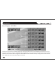
TM Parameter & Functions Set-up Guide LTO The display will revert to the default (switch-on) status and you will now see either a T and key icon, or P and key icon, signifying that the device is in Total or Partial Lock mode (Fig.6). Fig. 6 Partial Protection enabled Total Protection enabled T A 1 3 B24 S 5 6 2 U2 2W + 2 AX P A 1 3 B24 S 5 6 2 U2 2W + 2 AX Total Lock : Preset Selection: disabled . Delay Adjustment: disabled . All Edit functions: disabled . LCD Contrast: enabled .
Parameter & Functions Set-up Guide TM LTO The display should show UNLOCK, with Password below it and the first digit (represented by an asterisk '*') flashing (Fig.7). Use the rotary control to select the first digit of your chosen password, then use the right arrow key to move to the next digit and so on, until you have entered your full password. Now press ENTER. The LCD should now switch to the default display, without the key icon.
TM Your ALTO LTO R Warranty To be protected by this warranty, the buyer must be able to produce a numbered, machine printed sales receipt (original only accepted, not a copy) from his supplying dealer that clearly shows the dealer's name and address, the buyer's name and address, purchase date, model name/number and serial number of the product. ALTO reserves the right to verify the authenticity of the receipt directly with the supplying dealer.
SEKAKU ELECTRON CO., LTD. No. 1, Lane 17, Sec. 2, Han Shi W. Road, Taichung, 401 Taiwan http://www.altomobile.com Tel: 886-4-22313737 email: info@altomobile.com Fax: 886-4-22346757 All rights reserved to ALTO MOBILE. All features and content might be changed without prior notice. Any photocopy, translation, or reproduction of part of this manual without written permission is forbidden. Copyright c 2003 Sekaku Electron.