User's Manual X34 3-WAY STEREO/4-WAY MONO ACTIVE CROSSOVER R LTO www.altoproaudio.com Version 2.
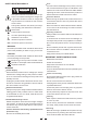
Fuse SAFETY RELATED SYMBOLS To prevent fire and damage to the product, use only the recommended fuse type as indicated in this manual. Do not short-circuit the fuse holder. Before replacing the fuse, make sure that the product is OFF and disconnected from the AC outlet. CAUTION RISK OF ELECTRIC SHOCK DO NOT OPEN This symbol, wherever used, alerts you to the presence of un-insulated and dangerous voltages within the product enclosure.
Preface Dear Customer: Thanks for choosing and researches. LTO Active Crossover and thanks for choosing the one of results of LTO AUDIO TEAM job For our LTO AUDIO TEAM, music and sound are more than a job...are first of all passion and let us say...our obsession! We have been designing professional audio products for a long time in cooperation with some of the major brands in the world in the audio field.
TABLE OF CONTENTS 1. INTRODUCTION ...................................................................................................................................4 2. FEATURE LIST ....................................................................................................................................4 3. CONTROL ELEMENTS.........................................................................................................................4 3.1 The Front Panel 3.2 The Rear Panel 4.
1. INTRODUCTION First we give our sincere appreciation for your confidence in LTO products by purchasing our X34 Active Crossover. It is the most effective support to us. The X34 Active Crossover is an ideal crossover and used universally in most small and large PA systems, recording studio monitors, DJ setups, commercial installations and live concerts. It is not only adaptable in mounting to different sound systems, but also it has many developed features.
14 15 16 17 18 19 20 21 Ch2 LOW Gain Ch2 LOW Mute Ch2 LOW-MID Crossover Frequency SUB Gain SUB Mute SUB-LOW Crossover Frequency Ch2 MID Gain Ch2 MID Mute Ch2 MID-HIGH Crossover Frequency LOW Gain LOW Mute LOW-MID Crossover Frequency Ch2 HIGH Gain Ch2 HIGH Mute MID Gain MID Mute Power switch: Turn the power on or off. Clip LED: It means that some band has resulted in clipping distortion when the LED is glittering. It is regarded as normal if it is glittering only one or two times.
Fuse holder & AC inlet Your unit may have the AC voltage selector ( 115V/60Hz or pull fuse-holder out and rotate 180 , then push in again. 230V/50Hz) built into the Fuse Holder. To change, Caution: The fuse protecting the AC supplies circuits of this unit. The fuse can only be changed by a qualified technician, in the event of a fault or changing the supply voltage. If the fuse continues to blow after replacing, discontinue use of this unit before repaired.
a. Wiring Configuration Either the 1/4" TRS (Tip-Ring-Sleeve) jack or the XLR servo connector can be wired in balanced and unbalanced modes. Please wire your systems as the following examples: For 1/4" Phone jack + + - Tip + Tip Ring Tip Ring Sleeve Sleeve TS Type Unbalanced Sleeve TRS Type Balanced TRS Type Unbalanced For XLR connector Pin2 (+) Pin2 (+) Pin3 (-) Pin3 (-) (Linked to Pin1 manually, ) Pin1 ( ) Pin1 ( ) XLR Type Unbalanced XLR Type Balanced b.
4.3 Rack Mounting The most secure mounting is on a universal rack shelf available from various rack manufactures or your music dealer. The X34 Active Crossover fits into one standard 19" rack unit of space. Please allow at least an additional 4" depth for the connectors on the rear panel. Be sure that there is enough air space around the unit for sufficient ventilation and please do not place the X34 Active Crossover on high temperature devices such as power amplifiers etc. to avoid overheating. 5.
5.2 X34 4-Way Mono To get such a typical application, configure your system and connect the wires in the following proper steps: 1. Press the mode switch to enter into the 4-way mono mode. 2. Apply the mono program source from the Mixer to the Input Connector of Channel 1. 3. Output the Sub frequencies signal to the power amplifier. 4. Output the Low frequencies signal to the power amplifier. 5. Output the Mid frequencies signal to the power amplifier. 6.
6. TECHNICAL SPECIFICATIONS Electrical: LOW-MID Frequency Range 90Hz-1KHz MID-HIGH Frequency Range 800Hz-10KHz Av=0db, fc=230Hz, 2.
7. WARRANTY 1. WARRANTY REGISTRATION CARD To obtain Warranty Service, the buyer should first fill out and return the enclosed Warranty Registration Card within 10 days of the Purchase Date. All the information presented in this Warranty Registration Card gives the manufacturer a better understanding of the sales status, so as to purport a more effective and efficient after-sales warranty service.
SEIKAKU TECHNICAL GROUP LIMITED No. 1, Lane 17, Sec. 2, Han Shi West Road, Taichung 40151 Taiwan http://www.altoproaudio.com Tel: 886-4-22313737 email: alto@altoproaudio.com Fax: 886-4-22346757 All rights reserved to ALTO. All features and content might be changed without prior notice. Any photocopy, translation, or reproduction of part of this manual without written permission is forbidden. Copyright c 2005 SEIKAKU GROUP NF 00860 -2.