ACM4 Series Access Power Controllers Installation Guide Models Include: ACM4 - Four (4) Fuse Protected Outputs ACM4E - Four (4) Fuse Protected Outputs w/Enclosure ACM4CB - Four (4) PTC Protected Outputs ACM4CBE - Four (4) PTC Protected Outputs w/Enclosure Rev. 082808 More than just power.
Overview: These units convert one (1) 12 to 24 volt AC or DC input into four (4) independently controlled fused or PTC protected outputs. These power outputs can be converted to dry form “C” contacts (ACM4/ACM4E only). Outputs are activated by an open collector sink or normally open (NO) dry trigger input from an Access Control System, Card Reader, Keypad, Push Button, PIR, etc.
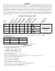
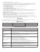
• Output ratings: - Fuses are rated 3 amp each. - PTCs are rated 2.5 amp each. • Main fuse is rated at 10 amp. Note: The total for all outputs combined is not to exceed 8 amp for ACM4CBE and 10 amp for ACM4E. (For Models ACM4/ACM4CB refer to the Total Output Chart on Page 2). Note: Operating temperature range should be 0 to +49oC. • Red LEDs indicate outputs are triggered (relays energized). • Fire Alarm disconnect (latching or non-latching) is individually selectable for any or all of the four (4) outputs.
connect the positive (+) input of the device being powered to the terminal marked [NC]. For Fail-Secure operation connect the positive (+) input of the device being powered to the terminal marked [NO]. (b) Form “C” outputs (ACM4/ACM4E): When form “C” outputs are desired the corresponding output fuse (1-4) must be removed. Connect negative (-) of the power supply directly to the locking device. Connect the positive (+) of the power supply to the terminal marked [C].
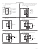
. Fire Alarm Interface options (Figs. 3 through 7, pg. 6): A normally closed [NC], normally open [NO] input or polarity reversal input from FACP signaling circuit will trigger selected outputs. To enable FACP Disconnect for an output open the corresponding switch [SW1-SW4]. To disable FACP disconnect for an output close the corresponding switch [SW1-SW4]. (a) Normally Open [NO] input: For non-latching hook-up (Fig. 4, pg. 6). For latching hook-up (Fig. 5, pg. 6).
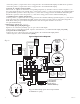
Hook-up Diagrams: Fig. 2 Optional hook-up using two (2) isolated power supply inputs: CUT JUMPERS J1 AND J2 ISOLATED POWER INPUT 12 OR 24VAC OR VDC (LOCK POWER) J3 TRG + INP --- T + RET --INTERFACE ISOLATED POWER INPUT 12 OR 24VAC OR VDC (ACM4 POWER) FACP CONTROL CIRCUIT EOL (if employed) FACP -- FROM + CONTROL CIRCUIT NO C NC FACP --- + Control CUT JUMPER J3 --- + Power J2 J1 Fig.
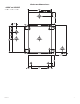
Enclosure Dimensions: • ACM4E and ACM4CBE 8.5"H x 7.5"W x 3.
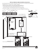
UL Listed Sub-Assembly Installation Instructions: The following Altronix sub-assembly modules may be field installed in the AL300ULX(R), AL600ULX(R), AL400ULX(R) power supply/chargers: ACM4 or ACM4CB 1. Disconnect power before proceeding with sub-assembly installation. 2. Fasten stand-offs (supplied) to the corresponding studs in the enclosure. 3. Align mounting holes of sub-assembly with stand-offs (Fig. 8, pg. 8). Refer below for the location and position for placement of sub-assembly. 4.