
ACM4-Series Instructions

ACM4 series - 3 -
• Output ratings:
- Fuses are rated 3 amp each.
- PTCs are rated 2.5 amp each.
• Main fuse is rated at 10 amp.
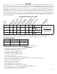
Note: The total for all outputs combined is not to exceed 8 amp for ACM4CBE and 10 amp for ACM4E.
(For Models ACM4/ACM4CB refer to the Total Output Chart on Page 2).
Note: Operating temperature range should be 0 to +49
o
C.
• Red LEDs indicate outputs are triggered (relays energized).
• Fire Alarm disconnect (latching or non-latching) is individually selectable for any or all of the four (4) outputs.
Fire Alarm disconnect input options:
a) Normally open (NO) or normally closed (NC) dry contact input.
b) Polarity reversal input from FACP signaling circuit.
• FACP output relay (form “C” contact rated @ 1 amp 28VDC not evaluated by UL).
• Green LED indicates when FACP disconnect is triggered.
• Removable terminal blocks facilitate ease of installation.
Board Dimensions (approximate): 5.125”L x 3.625”W x 1.25”H (ACM4 and ACM4CB).
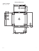
Enclosure Dimensions (approximate): 8.5”H x 7.5”W x 3.5”D (ACM4E and ACM4CBE).
Installation Instructions:
Wiring methods shall be in accordance with the National Electrical Code/NFPA 70/ANSI, and with all local codes and
authorities having jurisdiction. Product is intended for indoor use only.
1. For ACM4/ACM4CB sub-assembly boards, use stand-offs to mount only in AL300ULX, AL400ULX or
AL600ULX enclosures (Figs. 8-9, pg. 8). For ACM4E/ACM4CBE units, mount in desired location.
The enclosure door for the ACM4E/A
CM4CBE can be fastened by using either a cam lock or screws (both supplied).
Mark and predrill holes in the wall to line up with the top two keyholes in the enclosure. Install three upper
fasteners and screws in the wall with the screw heads protruding. Place the enclosure’s upper keyholes over the two
upper screws, level and secure. Mark the position of the lower three holes. Remove the enclosure. Drill the lower
holes and install the two fasteners. Place the enclosure’s upper keyholes over the two upper screws. Install the
two lower screws and make sure to tighten all screws (Enclosure Dimensions, pg. 7).
Carefully review:
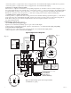
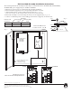
Typical Application Dia
gram (pg. 4) Terminal Identification Table (pg. 5)
LED Diagnostics (pg. 5) Hook-up Diagrams (pg. 6)
2. Power supply input:
The units can be powered with one (1) Listed Access Control Power Supply which will provide power for both
board operation and the locking devices or two (2) separate Listed Access Control Power Supplies, one (1) to provide
po
wer for the board operation and the other to provide power for the locking devices and/or access control hardware.
Note: The input power can be either 12 to 24 volts AC or DC operation.
Input Ratings (ACM4/A
CM4CB only):
- 12VDC @ .4 amp or 24VDC @ .2 amp.
Input Ratings (ACM4E/ACM4CBE only):
- 12VDC @ .4 amp or 24VDC @ .2 amp.
- 12VAC @ .4 amp or 24VAC @ .3 amp.
(a) Single power supply input:
If the unit and the locking devices are to be powered using a single Listed Access Control Power Supply, connect
the output (12 to 24 v
olts AC or DC) to the terminals marked [- Control +].
(b) Dual po
wer supply inputs (Fig. 1, pg. 4):
When the use of two Listed Access Control P
ower Supplies is desired, jumpers J1 and J2 (located to the left
of the power/control terminals) must be cut. Connect power for the unit to the terminals marked [- Control +]
and connect power for the locking devices to the terminals marked [- Power +].
Note: When using DC Listed Access Control Power Supplies polarity must be observed. When using AC Listed
Access Control P
ower Supplies polarity need not be observed.
Note: For UL compliance the power supplies must be UL Listed for Access Control Systems and accessories.
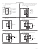
3. Output options (Fig. 1, pg. 4):
The ACM4/ACM4E will provide either four (4) switched power outputs, four (4) dry form “C” outputs, or
an
y combination of of both switched power and form “C” outputs, plus four (4) unswitched auxiliary power outputs.
The ACM4CB/ACM4CBE will provide four (4) switched power outputs or four (4) unswitched auxiliary power outputs.
(a) Switched Power outputs:
Connect the negative (-) input of the device being powered to the terminal marked [COM]. For Fail-Safe operation